Information injection-pump assembly
ZEXEL
106961-1511
1069611511
Rating:
Service parts 106961-1511 INJECTION-PUMP ASSEMBLY:
1.
_
2.
FUEL INJECTION PUMP
6.
COUPLING PLATE
7.
COUPLING PLATE
8.
_
9.
_
11.
Nozzle and Holder
1-15300-163-2
12.
Open Pre:MPa(Kqf/cm2)
15.7{160}/22.1{225}

15.
NOZZLE SET
Include in #1:
106961-1511
as INJECTION-PUMP ASSEMBLY
Cross reference number
ZEXEL
106961-1511
1069611511
Zexel num
Bosch num
Firm num
Name
Calibration Data:
Adjustment conditions
Test oil
1404 Test oil ISO4113 or {SAEJ967d}
1404 Test oil ISO4113 or {SAEJ967d}
Test oil temperature
degC
40
40
45
Nozzle and nozzle holder
105780-8140
Bosch type code
EF8511/9A
Nozzle
105780-0000
Bosch type code
DN12SD12T
Nozzle holder
105780-2080
Bosch type code
EF8511/9
Opening pressure
MPa
17.2
Opening pressure
kgf/cm2
175
Injection pipe
Outer diameter - inner diameter - length (mm) mm 8-3-600
Outer diameter - inner diameter - length (mm) mm 8-3-600
Overflow valve (drive side)
134424-3520
Overflow valve opening pressure (drive side)
kPa
255
221
289
Overflow valve opening pressure (drive side)
kgf/cm2
2.6
2.25
2.95
Overflow valve (governor side)
134424-2720
Overflow valve opening pressure (governor side)
kPa
255
221
289
Overflow valve opening pressure (governor side)
kgf/cm2
2.6
2.25
2.95
Tester oil delivery pressure
kPa
157
157
157
Tester oil delivery pressure
kgf/cm2
1.6
1.6
1.6
Direction of rotation (viewed from drive side)
Right R
Right R
Injection timing adjustment
Direction of rotation (viewed from drive side)
Right R
Right R
Injection order
1-8-7-6-
5-4-3-10
-9-2
Pre-stroke
mm
4.4
4.37
4.43
Beginning of injection position
Governor side NO.1
Governor side NO.1
Difference between angles 1
Cal 1-8 deg. 27 26.75 27.25
Cal 1-8 deg. 27 26.75 27.25
Difference between angles 2
Cal 1-7 deg. 72 71.75 72.25
Cal 1-7 deg. 72 71.75 72.25
Difference between angles 3
Cal 1-6 deg. 99 98.75 99.25
Cal 1-6 deg. 99 98.75 99.25
Difference between angles 4
Cal 1-5 deg. 144 143.75 144.25
Cal 1-5 deg. 144 143.75 144.25
Difference between angles 5
Cal 1-4 deg. 171 170.75 171.25
Cal 1-4 deg. 171 170.75 171.25
Difference between angles 6
Cal 1-3 deg. 216 215.75 216.25
Cal 1-3 deg. 216 215.75 216.25
Difference between angles 7
Cal 1-10 deg. 243 242.75 243.25
Cal 1-10 deg. 243 242.75 243.25
Difference between angles 8
Cal 1-9 deg. 288 287.75 288.25
Cal 1-9 deg. 288 287.75 288.25
Difference between angles 9
Cyl.1-2 deg. 315 314.75 315.25
Cyl.1-2 deg. 315 314.75 315.25
Injection quantity adjustment
Adjusting point
A
Rack position
7.9
Pump speed
r/min
800
800
800
Average injection quantity
mm3/st.
87.4
85.9
88.9
Max. variation between cylinders
%
0
-2
2
Basic
*
Fixing the lever
*
Injection quantity adjustment_02
Adjusting point
C
Rack position
7.9
Pump speed
r/min
1150
1150
1150
Average injection quantity
mm3/st.
94.5
90.5
98.5
Max. variation between cylinders
%
0
-3
3
Fixing the lever
*
Injection quantity adjustment_03
Adjusting point
D
Rack position
5.2+-0.5
Pump speed
r/min
225
225
225
Average injection quantity
mm3/st.
8
6.6
9.4
Max. variation between cylinders
%
0
-13
13
Fixing the rack
*
Injection quantity adjustment_04
Adjusting point
F
Rack position
-
Pump speed
r/min
150
150
150
Average injection quantity
mm3/st.
137
137
Fixing the lever
*
Remarks
When manual lever is on the boost side
When manual lever is on the boost side
Test data Ex:
Governor adjustment
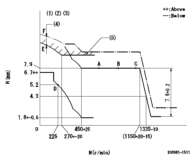
N:Pump speed
R:Rack position (mm)
(1)Supplied with damper spring not set.
(2)Supplied with torque spring not set.
(3)Supply solenoid operating voltage DC24V and move the solenoid body so that the excess lever reaches the excess position at the solenoid's maximum stroke.
(4)At excess fuel lever operation: not exceeding EXL
(5)Excess fuel setting for starting: SXL
----------
EXL=2mm SXL=9+-0.1mm
----------
----------
EXL=2mm SXL=9+-0.1mm
----------
Timer adjustment

(1)Adjusting range
(2)Step response time
(N): Speed of the pump
(L): Load
(theta) Advance angle
(Srd1) Step response time 1
(Srd2) Step response time 2
1. Adjusting conditions for the variable timer
(1)Adjust the clearance between the pickup and the protrusion to L.
----------
L=1-0.2(mm) N2=800r/min C2=(7.5)deg t1=1.5--sec. t2=1.5--sec.
----------
N1=950++r/min P1=0kPa(0kgf/cm2) P2=392kPa(4kgf/cm2) C1=7.5+-0.3deg R01=0/4load R02=4/4load
----------
L=1-0.2(mm) N2=800r/min C2=(7.5)deg t1=1.5--sec. t2=1.5--sec.
----------
N1=950++r/min P1=0kPa(0kgf/cm2) P2=392kPa(4kgf/cm2) C1=7.5+-0.3deg R01=0/4load R02=4/4load
Speed control lever angle

F:Full speed
----------
----------
a=6deg+-5deg
----------
----------
a=6deg+-5deg
0000000901

F:Full load
I:Idle
(1)Stopper bolt setting
----------
----------
a=10deg+-5deg b=33deg+-3deg
----------
----------
a=10deg+-5deg b=33deg+-3deg
Stop lever angle

N:Pump normal
S:Stop the pump.
----------
----------
a=60deg+-5deg b=73deg+-5deg
----------
----------
a=60deg+-5deg b=73deg+-5deg
0000001101
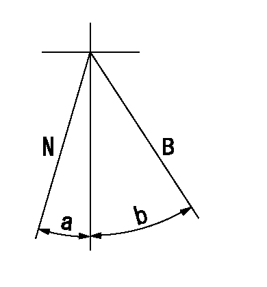
N:Normal
B:When boosted
----------
----------
a=(5deg) b=(24deg)
----------
----------
a=(5deg) b=(24deg)
0000001501 RACK SENSOR

V1:Supply voltage
V2f:Full side output voltage
V2i:Idle side output voltage
(A) Black
(B) Yellow
(C) Red
(D) Trimmer
(E): Shaft
(F) Nut
(G) Load lever
1. Load sensor adjustment
(1)Connect as shown in the above diagram and apply supply voltage V1.
(2)Hold the load lever (G) against the full side.
(3)Turn the shaft so that the voltage between (A) and (B) is V2.
(4)Hold the load lever (G) against the idle side.
(5)Adjust (D) so that the voltage between (A) and (B) is V2i.
(6)Repeat the above adjustments.
(7)Tighten the nut (F) at the point satisfying the standards.
(8)Hold the load lever against the full side stopper and the idle side stopper.
(9)At this time, confirm that the full side output voltage is V2f and the idle side output voltage is V2i.
----------
V1=5+-0.02V V2f=0.15+0.03V V2i=2.35-0.03V
----------
----------
V1=5+-0.02V V2f=0.15+0.03V V2i=2.35-0.03V
----------
Timing setting

(1)Pump vertical direction
(2)Position of "Z" mark at the No 1 cylinder's beginning of injection (governor side)
(3)B.T.D.C.: aa
(4)-
----------
aa=12deg
----------
a=(170deg)
----------
aa=12deg
----------
a=(170deg)
Information:
In order to avoid potential damage to your Cat machine and/or Cat engine, only purchase Cat fluids and Cat filters through your Cat dealer or Cat authorized outlets. For a list of authorized Cat parts outlets in your area, consult your Cat dealer.If you purchase what appear to be Cat fluids and/or Cat filters through other outlets/sources, you are at a very high risk of purchasing counterfeit ("look-alike") products.Counterfeit or "look-alike" products may visually appear the same as the original Cat product, but the product performance and internal quality will typically be very low.Counterfeit or "look-alike" products have a very high likelihood of causing and/or allowing engine and/or machine compartment damage.
Follow all industry standard safety practices when operating engines and/or machines and when performing all recommended and/or required maintenance.Note: Instructions for the installation of the filter are printed on the side of each Cat spin-on filter. For non-Cat filters, refer to the installation instructions that are provided by the supplier of the filter.
In order to meet expected fuel system component life, 4 micron(c) absolute or less secondary fuel filtration is required for all Cat diesel engines that are equipped with common-rail fuel systems. Also, 4 micron(c) absolute or less secondary fuel filtration is required for all Cat diesel engines that are equipped with unit injected fuel systems. For all other Cat diesel engines (mostly older engines with pump, line and nozzle type fuel systems), the use of 4 micron(c) absolute or less secondary fuel filtration is strongly recommended. Note that all current Cat diesel engines are factory equipped with Cat Advanced Efficiency 4 micron(c) absolute fuel filters.In order to obtain additional information on Cat designed and produced filtration products, refer to the "Reference Material" article, "Filters" and "Miscellaneous" topics in this Special Publication. Consult your Cat dealer for assistance with filtration recommendations for your Cat machine.
Caterpillar does not warrant the quality or performance of non-Caterpillar fluids and filters.
General Recommendations and Guidelines
Follow all applicable industry standards and all applicable governmental, environmental, and safety guidelines, practices, regulations, and mandates.Note: These general recommendations and guidelines concerning maintenance and care of fuel and fuel storage systems are not intended to be all inclusive. Discuss proper fuel safety and health, handling, and maintenance practices with your fuel supplier. Use of these general recommendations and guidelines does not lessen the engine owners and/or fuel supplier responsibility. All industry standard practices for fuel storage and for fuel handling must be followed.Note: Where recommendations for draining water and/or sediment and/or debris are stated, dispose of this waste according to all applicable regulations and mandates.Note: Cat filters are designed and built to provide optimal performance and protection of the fuel system components.
Discuss application-specific fuel concerns, needs, and requirements with a reputable fuel supplier.
Purchase fuel from a reputable supplier.
Use fuel that meets or exceeds Cat requirements for distillate diesel fuel. Refer to the "Cat Specification for Distillate Diesel Fuel for Nonroad Diesel Engines" table in this Special Publication, "Distillate Diesel Fuel" article.
Confirm with the filter manufacturer that the