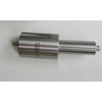
Information injection-pump assembly
ZEXEL
106961-1508
1069611508
ISUZU
1156032110
1156032110
Rating:
Service parts 106961-1508 INJECTION-PUMP ASSEMBLY:
1.
_
6.
COUPLING PLATE
7.
COUPLING PLATE
8.
_
9.
_
11.
Nozzle and Holder
12.
Open Pre:MPa(Kqf/cm2)
15.7(160)/22.1(225)
15.
NOZZLE SET
Include in #1:
106961-1508
as INJECTION-PUMP ASSEMBLY
Cross reference number
ZEXEL
106961-1508
1069611508
ISUZU
1156032110
1156032110
Zexel num
Bosch num
Firm num
Name
Calibration Data:
Adjustment conditions
Test oil
1404 Test oil ISO4113 or {SAEJ967d}
1404 Test oil ISO4113 or {SAEJ967d}
Test oil temperature
degC
40
40
45
Nozzle and nozzle holder
105780-8140
Bosch type code
EF8511/9A
Nozzle
105780-0000
Bosch type code
DN12SD12T
Nozzle holder
105780-2080
Bosch type code
EF8511/9
Opening pressure
MPa
17.2
Opening pressure
kgf/cm2
175
Injection pipe
Outer diameter - inner diameter - length (mm) mm 8-3-600
Outer diameter - inner diameter - length (mm) mm 8-3-600
Overflow valve (drive side)
134424-3520
Overflow valve opening pressure (drive side)
kPa
255
221
289
Overflow valve opening pressure (drive side)
kgf/cm2
2.6
2.25
2.95
Overflow valve (governor side)
134424-2720
Overflow valve opening pressure (governor side)
kPa
255
221
289
Overflow valve opening pressure (governor side)
kgf/cm2
2.6
2.25
2.95
Tester oil delivery pressure
kPa
157
157
157
Tester oil delivery pressure
kgf/cm2
1.6
1.6
1.6
Direction of rotation (viewed from drive side)
Right R
Right R
Injection timing adjustment
Direction of rotation (viewed from drive side)
Right R
Right R
Injection order
1-8-7-6-
5-4-3-10
-9-2
Pre-stroke
mm
4
3.97
4.03
Beginning of injection position
Governor side NO.1
Governor side NO.1
Difference between angles 1
Cal 1-8 deg. 27 26.75 27.25
Cal 1-8 deg. 27 26.75 27.25
Difference between angles 2
Cal 1-7 deg. 72 71.75 72.25
Cal 1-7 deg. 72 71.75 72.25
Difference between angles 3
Cal 1-6 deg. 99 98.75 99.25
Cal 1-6 deg. 99 98.75 99.25
Difference between angles 4
Cal 1-5 deg. 144 143.75 144.25
Cal 1-5 deg. 144 143.75 144.25
Difference between angles 5
Cal 1-4 deg. 171 170.75 171.25
Cal 1-4 deg. 171 170.75 171.25
Difference between angles 6
Cal 1-3 deg. 216 215.75 216.25
Cal 1-3 deg. 216 215.75 216.25
Difference between angles 7
Cal 1-10 deg. 243 242.75 243.25
Cal 1-10 deg. 243 242.75 243.25
Difference between angles 8
Cal 1-9 deg. 288 287.75 288.25
Cal 1-9 deg. 288 287.75 288.25
Difference between angles 9
Cyl.1-2 deg. 315 314.75 315.25
Cyl.1-2 deg. 315 314.75 315.25
Injection quantity adjustment
Adjusting point
A
Rack position
8.1
Pump speed
r/min
700
700
700
Average injection quantity
mm3/st.
85.6
84.1
87.1
Max. variation between cylinders
%
0
-2
2
Basic
*
Fixing the lever
*
Injection quantity adjustment_02
Adjusting point
B
Rack position
7.9+-0.5
Pump speed
r/min
1250
1250
1250
Average injection quantity
mm3/st.
95.9
91.9
99.9
Max. variation between cylinders
%
0
-3
3
Fixing the lever
*
Injection quantity adjustment_03
Adjusting point
C
Rack position
5.4+-0.5
Pump speed
r/min
225
225
225
Average injection quantity
mm3/st.
8
6.6
9.4
Max. variation between cylinders
%
0
-13
13
Fixing the rack
*
Injection quantity adjustment_04
Adjusting point
E
Rack position
-
Pump speed
r/min
150
150
150
Average injection quantity
mm3/st.
137
137
Fixing the lever
*
Remarks
When manual lever is on the boost side
When manual lever is on the boost side
Timer adjustment
Pump speed
r/min
750+50
Advance angle
deg.
0
0
0
Load
1/4
Remarks
Start
Start
Timer adjustment_02
Pump speed
r/min
1000+50
Advance angle
deg.
1
0.5
1
Load
3/4
Timer adjustment_03
Pump speed
r/min
(1075)
Advance angle
deg.
1
0.5
1
Load
4/4
Timer adjustment_04
Pump speed
r/min
1150
Advance angle
deg.
3
2.7
3.3
Load
4/4
Timer adjustment_05
Pump speed
r/min
1250
Advance angle
deg.
6
5.5
6.5
Load
4/4
Remarks
Finish
Finish
Test data Ex:
Governor adjustment
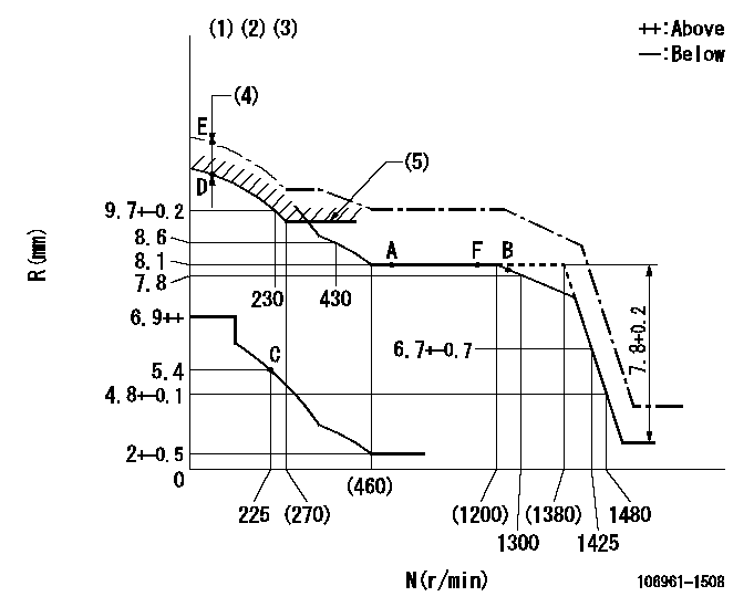
N:Pump speed
R:Rack position (mm)
(1)Tolerance for racks not indicated: +-0.05mm.
(2)Supplied with damper spring not set.
(3)Supply solenoid operating voltage DC24V and move the solenoid body so that the excess lever reaches the excess position at the solenoid's maximum stroke.
(4)At excess fuel lever operation: not exceeding EXL
(5)Excess fuel setting for starting: SXL (N = N1)
----------
EXL=2mm SXL=9.2+-0.1mm N1=320r/min
----------
----------
EXL=2mm SXL=9.2+-0.1mm N1=320r/min
----------
Speed control lever angle

F:Full speed
----------
----------
a=9deg+-5deg
----------
----------
a=9deg+-5deg
0000000901
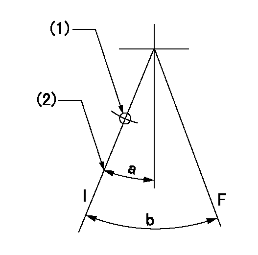
F:Full load
I:Idle
(1)Use the hole at R = aa
(2)Stopper bolt setting
----------
aa=35mm
----------
a=10deg+-5deg b=33deg+-3deg
----------
aa=35mm
----------
a=10deg+-5deg b=33deg+-3deg
Stop lever angle
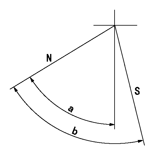
N:Pump normal
S:Stop the pump.
----------
----------
a=60deg+-5deg b=73deg+-5deg
----------
----------
a=60deg+-5deg b=73deg+-5deg
0000001101

N:Normal
B:When boosted
----------
----------
a=(5deg) b=(24deg)
----------
----------
a=(5deg) b=(24deg)
Timing setting
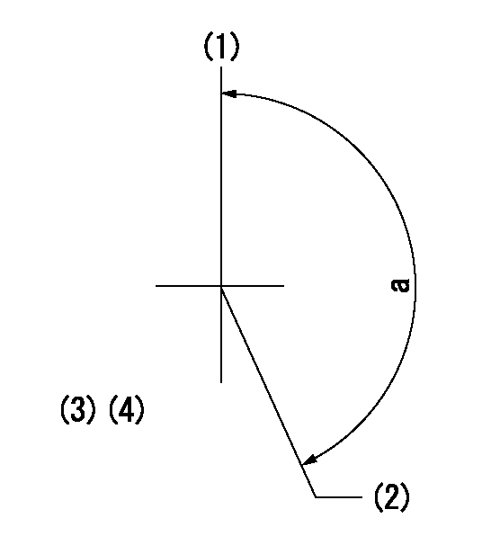
(1)Pump vertical direction
(2)Position of "Z" mark at the No 1 cylinder's beginning of injection (governor side)
(3)B.T.D.C.: aa
(4)-
----------
aa=12deg
----------
a=(170deg)
----------
aa=12deg
----------
a=(170deg)
Information:
The current API categories represent the minimum requirements for diesel engine oils. These categories are developed in collaboration of OEMs and the Oil and Chemical industries.The current licensed oils are:
API CK-4, released December 2016
API CJ-4, released 2006
API CI-4, API CI-4PLUS released 2002
API CH-4, released 1998Each API category is technically more advanced and of higher performance than the prior one.Refer to API 1509 document and/or ASTM D4485 for details of the API tests requirements and limits.Note: Obsolete API oil categories are not licensed by the API and hence are of uncontrolled quality. These oils are technically inferior to current oils and can result in reduced engine performance and life. These obsolete oil categories are not allowed in Cat engines.API FA-4 is NOT recommended for Caterpillar engines. API FA oil is designed with low High Temperature High Shear (HTHS) viscosity oil for use in certain 2017 On-Highway truck engines that have to meet certain on-road emissions regulations. This category is not backwards compatible.In order to help protect your engine, and in order to help optimize oil drain intervals for engine applications and duty cycles, use Cat S O S Services oil analysis. Refer to the section below and to the section on Cat S O S Services given later in the Special Publication.
Depending on application severity and localized environmental conditions, and also depending on maintenance practices, operating Direct Injection (DI) diesel engines and operating PC (Precombustion Chamber) diesel engines on fuel with sulfur levels over 0.1 percent (1000 ppm) may require significantly shortened oil change intervals in order to help maintain adequate wear protection. Refer to this Special Publication, "Fuel Specifications" section, “Diesel Fuel Sulfur” topic for additional information.
Fuel Sulfur Impact on Engine Oil
The use of Cat S O S Services oil analysis is recommended for determining oil life.For Caterpillar machines operating under emissions regulations such as US EPA Tier4, EU Stage V or other emission regulations controls, the maximum fuel sulfur level permitted by regulations in the US is 0.0015% or 15 ppm. Maximum permitted fuel sulfur levels in other emissions regulated countries may vary from .0015% or 15 ppm slightly and must be followed.In order to help protect your engine and optimize oil drain intervals for engine applications and duty cycles, it is important to use SOS Services oil analysis to determine if the sulfur has degraded the oil. Use Cat S O S Services oil analysis per the following general guidelines:
Recommended normally
For fuel sulfur level up to 0.05 percent (500 ppm), no additional sampling is required. Follow the recommended oil sampling in the machine OMM
For fuel sulfur level of > 0.05 percent to 0.5 percent (500 ppm to 5000 ppm), SOS services oil analysis is strongly recommended to determine oil drain intervals. Sample the oil every 250 hours until a trend is established,
