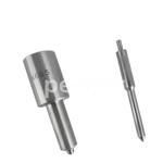
Information injection-pump assembly
ZEXEL
106961-1503
1069611503
Rating:
Service parts 106961-1503 INJECTION-PUMP ASSEMBLY:
1.
_
3.
GOVERNOR
6.
COUPLING PLATE
7.
COUPLING PLATE
8.
_
9.
_
11.
Nozzle and Holder
1-15300-163-2
12.
Open Pre:MPa(Kqf/cm2)
15.7{160}/22.1{225}
15.
NOZZLE SET
Include in #1:
106961-1503
as INJECTION-PUMP ASSEMBLY
Cross reference number
ZEXEL
106961-1503
1069611503
Zexel num
Bosch num
Firm num
Name
Calibration Data:
Adjustment conditions
Test oil
1404 Test oil ISO4113 or {SAEJ967d}
1404 Test oil ISO4113 or {SAEJ967d}
Test oil temperature
degC
40
40
45
Nozzle and nozzle holder
105780-8140
Bosch type code
EF8511/9A
Nozzle
105780-0000
Bosch type code
DN12SD12T
Nozzle holder
105780-2080
Bosch type code
EF8511/9
Opening pressure
MPa
17.2
Opening pressure
kgf/cm2
175
Injection pipe
Outer diameter - inner diameter - length (mm) mm 8-3-600
Outer diameter - inner diameter - length (mm) mm 8-3-600
Overflow valve (drive side)
134424-3520
Overflow valve opening pressure (drive side)
kPa
255
221
289
Overflow valve opening pressure (drive side)
kgf/cm2
2.6
2.25
2.95
Overflow valve (governor side)
134424-2720
Overflow valve opening pressure (governor side)
kPa
255
221
289
Overflow valve opening pressure (governor side)
kgf/cm2
2.6
2.25
2.95
Tester oil delivery pressure
kPa
157
157
157
Tester oil delivery pressure
kgf/cm2
1.6
1.6
1.6
Direction of rotation (viewed from drive side)
Right R
Right R
Injection timing adjustment
Direction of rotation (viewed from drive side)
Right R
Right R
Injection order
1-8-7-6-
5-4-3-10
-9-2
Pre-stroke
mm
4
3.97
4.03
Beginning of injection position
Governor side NO.1
Governor side NO.1
Difference between angles 1
Cal 1-8 deg. 27 26.75 27.25
Cal 1-8 deg. 27 26.75 27.25
Difference between angles 2
Cal 1-7 deg. 72 71.75 72.25
Cal 1-7 deg. 72 71.75 72.25
Difference between angles 3
Cal 1-6 deg. 99 98.75 99.25
Cal 1-6 deg. 99 98.75 99.25
Difference between angles 4
Cal 1-5 deg. 144 143.75 144.25
Cal 1-5 deg. 144 143.75 144.25
Difference between angles 5
Cal 1-4 deg. 171 170.75 171.25
Cal 1-4 deg. 171 170.75 171.25
Difference between angles 6
Cal 1-3 deg. 216 215.75 216.25
Cal 1-3 deg. 216 215.75 216.25
Difference between angles 7
Cal 1-10 deg. 243 242.75 243.25
Cal 1-10 deg. 243 242.75 243.25
Difference between angles 8
Cal 1-9 deg. 288 287.75 288.25
Cal 1-9 deg. 288 287.75 288.25
Difference between angles 9
Cyl.1-2 deg. 315 314.75 315.25
Cyl.1-2 deg. 315 314.75 315.25
Injection quantity adjustment
Adjusting point
B
Rack position
8.1
Pump speed
r/min
700
700
700
Average injection quantity
mm3/st.
85.6
84.1
87.1
Max. variation between cylinders
%
0
-2
2
Basic
*
Fixing the lever
*
Injection quantity adjustment_02
Adjusting point
C
Rack position
7.9+-0.5
Pump speed
r/min
1250
1250
1250
Average injection quantity
mm3/st.
95.9
91.9
99.9
Max. variation between cylinders
%
0
-3
3
Fixing the lever
*
Injection quantity adjustment_03
Adjusting point
D
Rack position
5.4+-0.5
Pump speed
r/min
225
225
225
Average injection quantity
mm3/st.
8
6.6
9.4
Max. variation between cylinders
%
0
-13
13
Fixing the rack
*
Injection quantity adjustment_04
Adjusting point
F
Rack position
-
Pump speed
r/min
150
150
150
Average injection quantity
mm3/st.
137
137
Fixing the lever
*
Remarks
When manual lever is on the boost side
When manual lever is on the boost side
Timer adjustment
Pump speed
r/min
750+50
Advance angle
deg.
0
0
0
Load
1/4
Remarks
Start
Start
Timer adjustment_02
Pump speed
r/min
1000+50
Advance angle
deg.
1
0.5
1
Load
3/4
Timer adjustment_03
Pump speed
r/min
(1075)
Advance angle
deg.
1
0.5
1
Load
4/4
Timer adjustment_04
Pump speed
r/min
1150
Advance angle
deg.
3
2.7
3.3
Load
4/4
Timer adjustment_05
Pump speed
r/min
1250
Advance angle
deg.
6
5.5
6.5
Load
4/4
Remarks
Finish
Finish
Test data Ex:
Governor adjustment
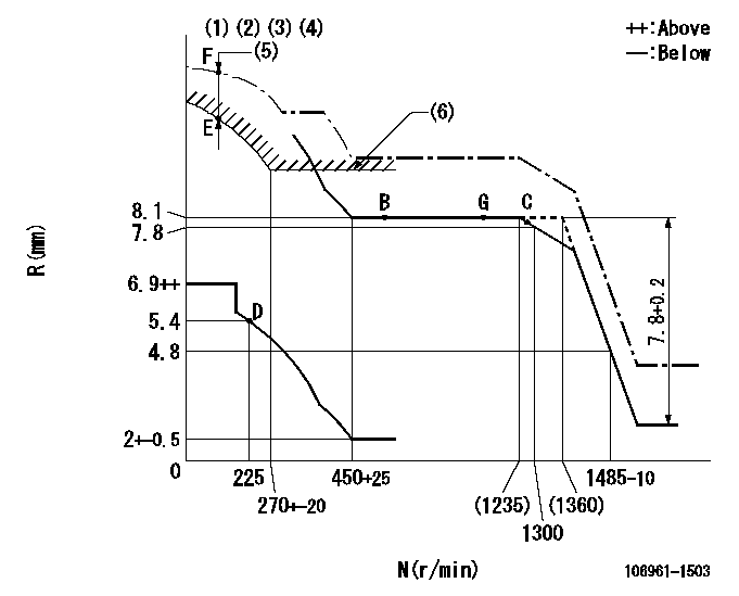
N:Pump speed
R:Rack position (mm)
(1)Lever ratio: RT
(2)Target shim dimension: TH
(3)Supplied with damper spring not set.
(4)Supply solenoid operating voltage DC24V and move the solenoid body so that the excess lever reaches the excess position at the solenoid's maximum stroke.
(5)At excess fuel lever operation: not exceeding EXL
(6)Excess fuel setting for starting: SXL
----------
RT=0.8 TH=2.3mm EXL=2mm SXL=9.2+-0.1mm
----------
----------
RT=0.8 TH=2.3mm EXL=2mm SXL=9.2+-0.1mm
----------
Speed control lever angle

F:Full speed
----------
----------
a=9deg+-5deg
----------
----------
a=9deg+-5deg
0000000901
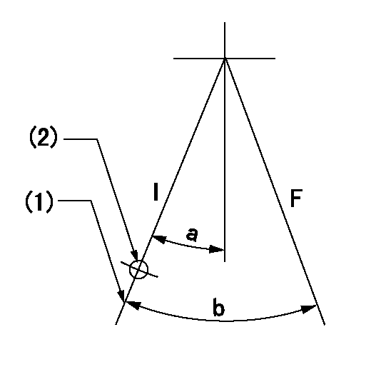
F:Full load
I:Idle
(1)Stopper bolt setting
(2)Use the hole at R = aa
----------
aa=35mm
----------
a=10deg+-5deg b=33deg+-3deg
----------
aa=35mm
----------
a=10deg+-5deg b=33deg+-3deg
Stop lever angle
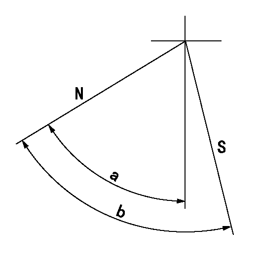
N:Pump normal
S:Stop the pump.
----------
----------
a=60deg+-5deg b=73deg+-5deg
----------
----------
a=60deg+-5deg b=73deg+-5deg
0000001101

N:Normal
B:When boosted
----------
----------
a=(5deg) b=(24deg)
----------
----------
a=(5deg) b=(24deg)
Timing setting
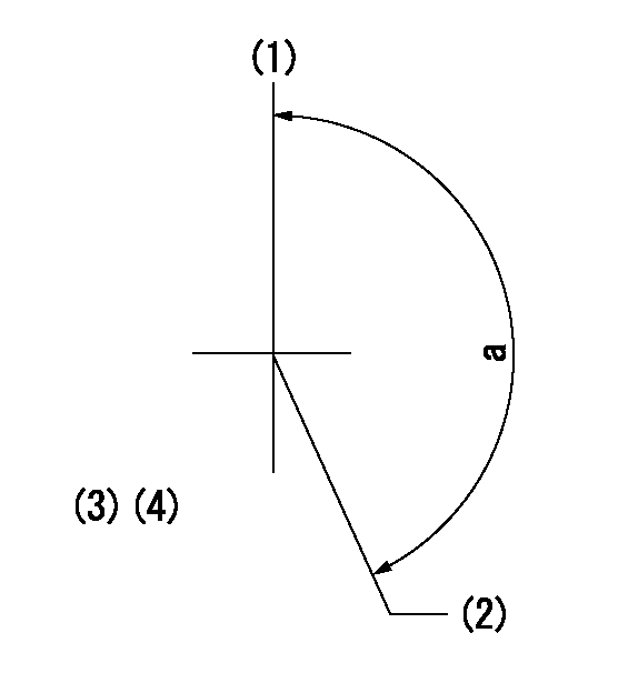
(1)Pump vertical direction
(2)Position of "Z" mark at the No 1 cylinder's beginning of injection (governor side)
(3)B.T.D.C.: aa
(4)-
----------
aa=12deg
----------
a=(170deg)
----------
aa=12deg
----------
a=(170deg)
Information:
Recommended engine warm-up procedure must be followed. Refer to the engine Operation and Maintenance Manual. Also refer to the relevant “Lubricant Viscosities for Ambient Temperatures” table footnote in this Special Publication.
Excessive engine idling time can contribute to excessive water in the crankcase oil, causing corrosion, sludge, and other problems. Excessive engine idling time can also lead to injector fouling, piston and combustion chamber deposits, corrosive damage, and increased oil consumption.
For proper selection of oil viscosity grade and oil type and/or specification, refer to this Special Publication, "Lubricant Specifications" section.Also, refer to this Special Publication, "Lubricant Viscosities" article.
Not following the recommendations found in the “Lubricant Viscosities for Ambient Temperatures” table and associated footnotes can lead to reduced performance and engine failure.
Do NOT use only the oil viscosities when determining the recommended oil for an engine compartment. The oil type (performance requirements) MUST also be used.
For easier cold weather starting, make sure that all of the components of the engine electrical system are properly maintained. All electrical wiring and connections should be free of the following: fraying, damaged insulation and corrosion. Batteries should be kept fully charged and warm. The batteries and the battery cables must be sized properly for the application.Various starting aids are available in order to assist with cold engine starts in low temperature conditions. Follow the recommendations that are provided by the manufacturer of the starting aid. Refer to the foreword section of this Special Publication, "Aftermarket Products and Warranty".For additional information concerning cold-weather operation, refer to this Special Publication, "Fuel Specifications" section. Also refer to this Special Publication, "Cooling System Specifications" section.Before attempting to start the engine, make sure that the oil in the engine is fluid enough to flow. Check the oil by removing the dipstick. If the oil will drip from the dipstick, then the oil should be fluid enough to allow the engine to start. Do not use oil that has been diluted with kerosene. Kerosene will evaporate in the engine. and cause the oil to thicken. Kerosene will cause swelling and softening of the silicone seals. Kerosene will dilute the oil additives. Dilution of the oil additives will reduce the performance, and reduce the engine protection that the additives provide.If the viscosity of the oil is changed for colder weather, also change the filter element. If the filter is not changed, the filter element and the filter housing can become a solid mass. After you change the oil, operate the engine in order to circulate the thinner oil.When you start a cold-soaked engine or when you operate an engine in ambient temperatures that are below −18°C (0°F), use base oils that can flow in low temperatures. These multigrade oils have lubricant viscosity grade of
