Information injection-pump assembly
ZEXEL
106961-1499
1069611499
ISUZU
1156027382
1156027382
Rating:
Service parts 106961-1499 INJECTION-PUMP ASSEMBLY:
1.
_
6.
COUPLING PLATE
7.
COUPLING PLATE
8.
_
9.
_
11.
Nozzle and Holder
12.
Open Pre:MPa(Kqf/cm2)
15.7(160)/22.1(225)

15.
NOZZLE SET
Include in #1:
106961-1499
as INJECTION-PUMP ASSEMBLY
Cross reference number
ZEXEL
106961-1499
1069611499
ISUZU
1156027382
1156027382
Zexel num
Bosch num
Firm num
Name
Calibration Data:
Adjustment conditions
Test oil
1404 Test oil ISO4113 or {SAEJ967d}
1404 Test oil ISO4113 or {SAEJ967d}
Test oil temperature
degC
40
40
45
Nozzle and nozzle holder
105780-8140
Bosch type code
EF8511/9A
Nozzle
105780-0000
Bosch type code
DN12SD12T
Nozzle holder
105780-2080
Bosch type code
EF8511/9
Opening pressure
MPa
17.2
Opening pressure
kgf/cm2
175
Injection pipe
Outer diameter - inner diameter - length (mm) mm 8-3-600
Outer diameter - inner diameter - length (mm) mm 8-3-600
Overflow valve (drive side)
134424-3520
Overflow valve opening pressure (drive side)
kPa
255
221
289
Overflow valve opening pressure (drive side)
kgf/cm2
2.6
2.25
2.95
Overflow valve (governor side)
134424-2720
Overflow valve opening pressure (governor side)
kPa
255
221
289
Overflow valve opening pressure (governor side)
kgf/cm2
2.6
2.25
2.95
Tester oil delivery pressure
kPa
157
157
157
Tester oil delivery pressure
kgf/cm2
1.6
1.6
1.6
Direction of rotation (viewed from drive side)
Right R
Right R
Injection timing adjustment
Direction of rotation (viewed from drive side)
Right R
Right R
Injection order
1-8-7-6-
5-4-3-10
-9-2
Pre-stroke
mm
4
3.97
4.03
Beginning of injection position
Governor side NO.1
Governor side NO.1
Difference between angles 1
Cal 1-8 deg. 27 26.75 27.25
Cal 1-8 deg. 27 26.75 27.25
Difference between angles 2
Cal 1-7 deg. 72 71.75 72.25
Cal 1-7 deg. 72 71.75 72.25
Difference between angles 3
Cal 1-6 deg. 99 98.75 99.25
Cal 1-6 deg. 99 98.75 99.25
Difference between angles 4
Cal 1-5 deg. 144 143.75 144.25
Cal 1-5 deg. 144 143.75 144.25
Difference between angles 5
Cal 1-4 deg. 171 170.75 171.25
Cal 1-4 deg. 171 170.75 171.25
Difference between angles 6
Cal 1-3 deg. 216 215.75 216.25
Cal 1-3 deg. 216 215.75 216.25
Difference between angles 7
Cal 1-10 deg. 243 242.75 243.25
Cal 1-10 deg. 243 242.75 243.25
Difference between angles 8
Cal 1-9 deg. 288 287.75 288.25
Cal 1-9 deg. 288 287.75 288.25
Difference between angles 9
Cyl.1-2 deg. 315 314.75 315.25
Cyl.1-2 deg. 315 314.75 315.25
Injection quantity adjustment
Adjusting point
B
Rack position
8.1
Pump speed
r/min
700
700
700
Average injection quantity
mm3/st.
85.6
84.1
87.1
Max. variation between cylinders
%
0
-2
2
Basic
*
Fixing the lever
*
Injection quantity adjustment_02
Adjusting point
C
Rack position
7.9+-0.5
Pump speed
r/min
1250
1250
1250
Average injection quantity
mm3/st.
95.9
91.9
99.9
Max. variation between cylinders
%
0
-3
3
Fixing the lever
*
Injection quantity adjustment_03
Adjusting point
D
Rack position
5.4+-0.5
Pump speed
r/min
225
225
225
Average injection quantity
mm3/st.
8
6.6
9.4
Max. variation between cylinders
%
0
-13
13
Fixing the rack
*
Injection quantity adjustment_04
Adjusting point
F
Rack position
-
Pump speed
r/min
150
150
150
Average injection quantity
mm3/st.
137
137
Fixing the lever
*
Remarks
When manual lever is on the boost side
When manual lever is on the boost side
Test data Ex:
Governor adjustment
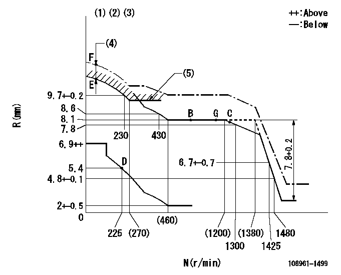
N:Pump speed
R:Rack position (mm)
(1)Tolerance for racks not indicated: +-0.05mm.
(2)Supplied with damper spring not set.
(3)Supply solenoid operating voltage DC24V and move the solenoid body so that the excess lever reaches the excess position at the solenoid's maximum stroke.
(4)At excess fuel lever operation: not exceeding EXL
(5)Excess fuel setting for starting: SXL (N = N1)
----------
EXL=2mm SXL=9.2+-0.1mm N1=320r/min
----------
----------
EXL=2mm SXL=9.2+-0.1mm N1=320r/min
----------
Timer adjustment

(1)Adjusting range
(2)Step response time
(N): Speed of the pump
(L): Load
(theta) Advance angle
(Srd1) Step response time 1
(Srd2) Step response time 2
1. Adjusting conditions for the variable timer
(1)Adjust the clearance between the pickup and the protrusion to L.
----------
L=1-0.2mm N2=800r/min C2=(7)deg t1=1.5--sec. t2=1.5--sec.
----------
N1=1100++r/min P1=0kPa(0kgf/cm2) P2=392kPa(4kgf/cm2) C1=7+-0.3deg R01=0/4load R02=4/4load
----------
L=1-0.2mm N2=800r/min C2=(7)deg t1=1.5--sec. t2=1.5--sec.
----------
N1=1100++r/min P1=0kPa(0kgf/cm2) P2=392kPa(4kgf/cm2) C1=7+-0.3deg R01=0/4load R02=4/4load
Speed control lever angle

F:Full speed
----------
----------
a=9deg+-5deg
----------
----------
a=9deg+-5deg
0000000901
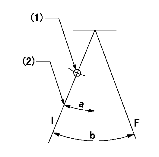
F:Full load
I:Idle
(1)Use the hole at R = aa
(2)Stopper bolt setting
----------
aa=35mm
----------
a=10deg+-5deg b=33deg+-3deg
----------
aa=35mm
----------
a=10deg+-5deg b=33deg+-3deg
Stop lever angle

N:Pump normal
S:Stop the pump.
----------
----------
a=60deg+-5deg b=73deg+-5deg
----------
----------
a=60deg+-5deg b=73deg+-5deg
0000001101

N:Normal
B:When boosted
----------
----------
a=(5deg) b=(24deg)
----------
----------
a=(5deg) b=(24deg)
0000001501 RACK SENSOR

V1:Supply voltage
V2f:Full side output voltage
V2i:Idle side output voltage
(A) Black
(B) Yellow
(C) Red
(D) Trimmer
(E): Shaft
(F) Nut
(G) Load lever
1. Load sensor adjustment
(1)Connect as shown in the above diagram and apply supply voltage V1.
(2)Hold the load lever (G) against the full side.
(3)Turn the shaft so that the voltage between (A) and (B) is V2.
(4)Hold the load lever (G) against the idle side.
(5)Adjust (D) so that the voltage between (A) and (B) is V2i.
(6)Repeat the above adjustments.
(7)Tighten the nut (F) at the point satisfying the standards.
(8)Hold the load lever against the full side stopper and the idle side stopper.
(9)At this time, confirm that the full side output voltage is V2f and the idle side output voltage is V2i.
----------
V1=5+-0.02V V2f=0.15+0.03V V2i=2.35-0.03V
----------
----------
V1=5+-0.02V V2f=0.15+0.03V V2i=2.35-0.03V
----------
Timing setting

(1)Pump vertical direction
(2)Position of "Z" mark at the No 1 cylinder's beginning of injection (governor side)
(3)B.T.D.C.: aa
(4)-
----------
aa=12deg
----------
a=(170deg)
----------
aa=12deg
----------
a=(170deg)
Information:
Registering a New DEF Injector Injection Timing, Serial Number, and Part Number
Record the DEF injector trim code & part number.
Illustration 10 g06075057
(6) DEF Injector Injection Timing
(7) Part Number
Illustration 11 g06075059
(8) DEF Injector Serial Number
Record the DEF injector Serial Number.
Go to SIS.
Select "View More".
Select "Additional Service Information".
Select "C2.4, C3.3B" and "C3.8 Downloads".
Select ECU Trim Data Registration (Injector, Injection Timing, or DEF Injector).
Illustration 12 g06070579
Input the 6 or 7-digit code engine serial number. Refer to "General Information" to locate the serial number.
Click the button to select the engine.
Enter the new DEF injector part number, Serial number, and injection timing.
Illustration 13 g06075064
Once the new DEF injector Part number, Serial number and Injection timing values have been registered you may follow the DCU flashing procedure to obtain the new DPK flash file found in REHS9223, "Electronic Control Module (ECM) & Dosing Control Unit (DCU Flashing Procedure for the C2.4, C3.3B and C3.8 Engines".Note: Following the above procedure will ensure that any future DCU reflashing will flash the correct DEF injector information.New DEF Injector Install within Electronic Technician (ET)
The Caterpillar Electronic Technician (ET) is used to load injector trim files into the Engine Control Module (ECM).Replacing a DEF Injector
A new DEF Injection Timing Correction must be loaded into the DCU if an injector is replaced through Caterpillar Electronic Technician (ET).Replacing the DCU
Prior to replacing a DCU, It is recommended to download a Product Status Report for documentation of the DEF Injector. After replacing the DCU, ensure the DEF injector trim codes in the new DCU match the saved Product Status Report.
Establish communication between Cat ET and the engine ECM. Refer to Troubleshooting, "Electronic Service Tools", if necessary.
Select the following menu options on Cat ET:
Service
Calibrations
Diesel Exhaust Fluid Controller #1
Injector Code Calibration
Illustration 14 g06070577
Select Injector 1
Illustration 15 g06070578
Enter the new "DEF Injection Timing" Current Value.
Click the "Change" button.Registering (Fuel) Injection Timing Correction
The following steps are to be followed when the fuel injection timing correction procedure has been performed and the engine ecm must be updates with the new value.Note: This procedure is only performed if the crankshaft, gear case, crank gear, or flywheel is replaced. Refer to the following engine specific Special Instructions for determining Injection Timing Correction.C2.4 , M0084937C3.3B , M0084939C3.8 , M0084935
Illustration 16 g06220029
Got to SIS web. Select C2.4, C3.3B, and C3.8 Downloads.
Illustration 17 g06220033
Select ECU and DCU Trim Data Registration.
Illustration 18 g06220036
Engine Serial Number and select search. Engine Serial Number is case-sensitive.
Illustration 19 g06220038
Click the circle (indicated by red arrow) and wait for the screen to change.
Illustration 20 g06220042
Scroll down until Injection Timing Correction is displayed. Enter new value, scroll to the bottom of page, and select Register.
Once the new Injection Timing Correction value has been registered a new DPK file will need to be downloaded and flashed to the Engine ECM. Refer to , REHS9223, "Electronic Control Module (ECM) & Dosing Control Unit (DCU) Flashing Procedure for the C2.4, C3.3B and C3.8 Engines".