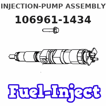
Information injection-pump assembly
ZEXEL
106961-1434
1069611434
ISUZU
1156015734
1156015734
Rating:
Service parts 106961-1434 INJECTION-PUMP ASSEMBLY:
1.
_
6.
COUPLING PLATE
7.
COUPLING PLATE
8.
_
9.
_

11.
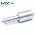
Nozzle and Holder
12.
Open Pre:MPa(Kqf/cm2)
19.6(200)
15.
NOZZLE SET
Include in #1:
106961-1434
as INJECTION-PUMP ASSEMBLY
Cross reference number
ZEXEL
106961-1434
1069611434
ISUZU
1156015734
1156015734
Zexel num
Bosch num
Firm num
Name
Calibration Data:
Adjustment conditions
Test oil
1404 Test oil ISO4113 or {SAEJ967d}
1404 Test oil ISO4113 or {SAEJ967d}
Test oil temperature
degC
40
40
45
Nozzle and nozzle holder
105780-8140
Bosch type code
EF8511/9A
Nozzle
105780-0000
Bosch type code
DN12SD12T
Nozzle holder
105780-2080
Bosch type code
EF8511/9
Opening pressure
MPa
17.2
Opening pressure
kgf/cm2
175
Injection pipe
Outer diameter - inner diameter - length (mm) mm 8-3-600
Outer diameter - inner diameter - length (mm) mm 8-3-600
Overflow valve opening pressure
kPa
157
123
191
Overflow valve opening pressure
kgf/cm2
1.6
1.25
1.95
Tester oil delivery pressure
kPa
157
157
157
Tester oil delivery pressure
kgf/cm2
1.6
1.6
1.6
Direction of rotation (viewed from drive side)
Right R
Right R
Injection timing adjustment
Direction of rotation (viewed from drive side)
Right R
Right R
Injection order
1-4-9-8-
5-2-11-1
0-3-6-7-
Pre-stroke
mm
4.4
4.37
4.43
Beginning of injection position
Governor side NO.1
Governor side NO.1
Difference between angles 1
Cal 1-4 deg. 15 14.75 15.25
Cal 1-4 deg. 15 14.75 15.25
Difference between angles 2
Cal 1-9 deg. 60 59.75 60.25
Cal 1-9 deg. 60 59.75 60.25
Difference between angles 3
Cal 1-8 deg. 75 74.75 75.25
Cal 1-8 deg. 75 74.75 75.25
Difference between angles 4
Cal 1-5 deg. 120 119.75 120.25
Cal 1-5 deg. 120 119.75 120.25
Difference between angles 5
Cyl.1-2 deg. 135 134.75 135.25
Cyl.1-2 deg. 135 134.75 135.25
Difference between angles 6
Cal 1-11 deg. 180 179.75 180.25
Cal 1-11 deg. 180 179.75 180.25
Difference between angles 7
Cal 1-10 deg. 195 194.75 195.25
Cal 1-10 deg. 195 194.75 195.25
Difference between angles 8
Cal 1-3 deg. 240 239.75 240.25
Cal 1-3 deg. 240 239.75 240.25
Difference between angles 9
Cal 1-6 deg. 255 254.75 255.25
Cal 1-6 deg. 255 254.75 255.25
Difference between angles 10
Cal 1-7 deg. 300 299.75 300.25
Cal 1-7 deg. 300 299.75 300.25
Difference between angles 11
Cal 1-12 deg. 315 314.75 315.25
Cal 1-12 deg. 315 314.75 315.25
Injection quantity adjustment
Adjusting point
A
Rack position
8.2
Pump speed
r/min
750
750
750
Average injection quantity
mm3/st.
101.4
99.9
102.9
Max. variation between cylinders
%
0
-2
2
Basic
*
Fixing the lever
*
Injection quantity adjustment_02
Adjusting point
D
Rack position
4.3+-0.5
Pump speed
r/min
250
250
250
Average injection quantity
mm3/st.
11
9.6
12.4
Max. variation between cylinders
%
0
-13
13
Fixing the rack
*
Timer adjustment
Pump speed
r/min
500+-50
Advance angle
deg.
0
0
0
Remarks
Start
Start
Timer adjustment_02
Pump speed
r/min
1250
Advance angle
deg.
5.5
5
6
Remarks
Finish
Finish
Test data Ex:
Governor adjustment
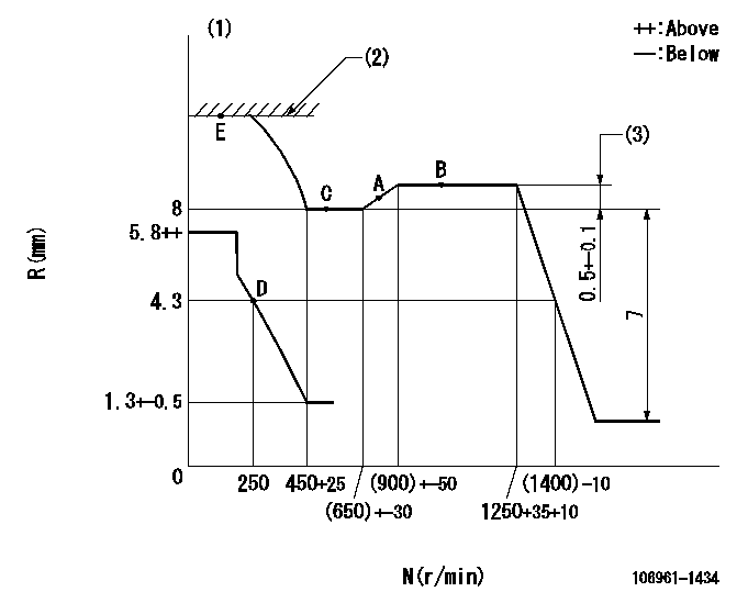
N:Pump speed
R:Rack position (mm)
(1)Damper spring does not operate.
(2)Excess fuel setting for starting: SXL
(3)Rack difference between N = N1 and N = N2
----------
SXL=11+0.2mm N1=1250r/min N2=500r/min
----------
----------
SXL=11+0.2mm N1=1250r/min N2=500r/min
----------
Speed control lever angle

F:Full speed
----------
----------
a=7deg+-5deg
----------
----------
a=7deg+-5deg
0000000901

F:Full load
I:Idle
(1)Stopper bolt setting
----------
----------
a=10deg+-5deg b=36deg+-3deg
----------
----------
a=10deg+-5deg b=36deg+-3deg
Stop lever angle

N:Pump normal
S:Stop the pump.
----------
----------
a=60deg+-5deg b=73deg+-5deg
----------
----------
a=60deg+-5deg b=73deg+-5deg
Timing setting

(1)Pump vertical direction
(2)Position of "Z" mark at the No 1 cylinder's beginning of injection (governor side)
(3)B.T.D.C.: aa
(4)-
----------
aa=16deg
----------
a=(170deg)
----------
aa=16deg
----------
a=(170deg)
Information:
Illustration 1 g00670863
CCM Cable requirements for Direct Connection to PC with 25 Pin Connector (1) PC with 25 pin RS-232C connector (2) 25 to 25 pin female to male cable (3) Null modem adapter (4) CCM with 25 pin RS-232C connectorIf the PC has a 9 pin RS-232C connector a 9 to 25 pin cable with a null modem adapter is required. Refer to Illustration 2.
Illustration 2 g00670882
CCM Cable Requirements for Direct Connection to PC with 9-Pin Connector (1) PC with 9 pin RS-232C connector (2) 9 to 25 pin cable (3) Null modem adapter (4) CCM with 25 pin RS-232C connectorThe null modem adapter connects the Data Transmit of one device to the Data Receive of the other device. The Null Modem adapter connects the Data Carrier Detect and the Data Terminal Ready pins in a similar manner. Cables are available from most personal computer suppliers.Note: Verify that the cables and null modem adapters are compatible with the specifications in Tables 1 and 2.
Table 1
25 PIN RS-232C PIN DEFINITIONS
Pin Number Description
2 Data Transmit (TX)
3 Data Receive (RX)
7 Ground
8 Data Carrier Detect (DCD)
20 Data Terminal Ready (DTR)
Table 2
9 PIN RS-232C PIN DEFINITIONS
Pin Number Description
1 Data Carrier Detect (DCD)
2 Data Receive (RX
3 Data Transmit (TX)
4 Data Terminal Ready (DTR)
5 Ground A 25 to 25 pin cable or a 9 to 25 pin cable is needed when the CCM is used with a modem. Refer to Illustrations 3 and 4. The type of cable will depend on the number of pins on the RS-232C connector of the PC.Note: Do not use a null modem adapter to connect a modem to the PC or the CCM.
Illustration 3 g00645279
CCM Cable Requirements for Modem Connection to PC with 9-Pin Connector (1) PC with 9 pin RS-232C connector (2) 9 to 25 pin cable (3) Modems that are connected by telephone lines (4) 25 to 25 pin cable (5) CCM with 25 pin RS-232C connector (6) Telephone line
Illustration 4 g00645341
CCM Cable Requirements for Modem Connection to PC with 25-Pin Connector (1) PC with 25 pin RS-232C connector (2) 25 to 25 pin cable (3) Modems that are connected by telephone lines (4) 25 to 25 pin cable (5) CCM with 25 pin RS-232C connector (6) Telephone line