Information injection-pump assembly
ZEXEL
106961-1424
1069611424
ISUZU
1156015724
1156015724

Rating:
Service parts 106961-1424 INJECTION-PUMP ASSEMBLY:
1.
_
6.
COUPLING PLATE
7.
COUPLING PLATE
8.
_
9.
_

11.
Nozzle and Holder
12.
Open Pre:MPa(Kqf/cm2)
19.6(200)
15.
NOZZLE SET
Include in #1:
106961-1424
as INJECTION-PUMP ASSEMBLY
Cross reference number
ZEXEL
106961-1424
1069611424
ISUZU
1156015724
1156015724
Zexel num
Bosch num
Firm num
Name
Calibration Data:
Adjustment conditions
Test oil
1404 Test oil ISO4113 or {SAEJ967d}
1404 Test oil ISO4113 or {SAEJ967d}
Test oil temperature
degC
40
40
45
Nozzle and nozzle holder
105780-8140
Bosch type code
EF8511/9A
Nozzle
105780-0000
Bosch type code
DN12SD12T
Nozzle holder
105780-2080
Bosch type code
EF8511/9
Opening pressure
MPa
17.2
Opening pressure
kgf/cm2
175
Injection pipe
Outer diameter - inner diameter - length (mm) mm 8-3-600
Outer diameter - inner diameter - length (mm) mm 8-3-600
Overflow valve opening pressure
kPa
157
123
191
Overflow valve opening pressure
kgf/cm2
1.6
1.25
1.95
Tester oil delivery pressure
kPa
157
157
157
Tester oil delivery pressure
kgf/cm2
1.6
1.6
1.6
Direction of rotation (viewed from drive side)
Right R
Right R
Injection timing adjustment
Direction of rotation (viewed from drive side)
Right R
Right R
Injection order
1-8-7-6-
5-4-3-10
-9-2
Pre-stroke
mm
4.4
4.37
4.43
Beginning of injection position
Governor side NO.1
Governor side NO.1
Difference between angles 1
Cal 1-8 deg. 27 26.75 27.25
Cal 1-8 deg. 27 26.75 27.25
Difference between angles 2
Cal 1-7 deg. 72 71.75 72.25
Cal 1-7 deg. 72 71.75 72.25
Difference between angles 3
Cal 1-6 deg. 99 98.75 99.25
Cal 1-6 deg. 99 98.75 99.25
Difference between angles 4
Cal 1-5 deg. 144 143.75 144.25
Cal 1-5 deg. 144 143.75 144.25
Difference between angles 5
Cal 1-4 deg. 171 170.75 171.25
Cal 1-4 deg. 171 170.75 171.25
Difference between angles 6
Cal 1-3 deg. 216 215.75 216.25
Cal 1-3 deg. 216 215.75 216.25
Difference between angles 7
Cal 1-10 deg. 243 242.75 243.25
Cal 1-10 deg. 243 242.75 243.25
Difference between angles 8
Cal 1-9 deg. 288 287.75 288.25
Cal 1-9 deg. 288 287.75 288.25
Difference between angles 9
Cyl.1-2 deg. 315 314.75 315.25
Cyl.1-2 deg. 315 314.75 315.25
Injection quantity adjustment
Adjusting point
A
Rack position
8.2
Pump speed
r/min
750
750
750
Average injection quantity
mm3/st.
101.4
99.9
102.9
Max. variation between cylinders
%
0
-2
2
Basic
*
Fixing the lever
*
Injection quantity adjustment_02
Adjusting point
D
Rack position
4.3+-0.5
Pump speed
r/min
250
250
250
Average injection quantity
mm3/st.
11
9.6
12.4
Max. variation between cylinders
%
0
-13
13
Fixing the rack
*
Timer adjustment
Pump speed
r/min
500+-50
Advance angle
deg.
0
0
0
Remarks
Start
Start
Timer adjustment_02
Pump speed
r/min
1250
Advance angle
deg.
5.5
5
6
Remarks
Finish
Finish
Test data Ex:
Governor adjustment
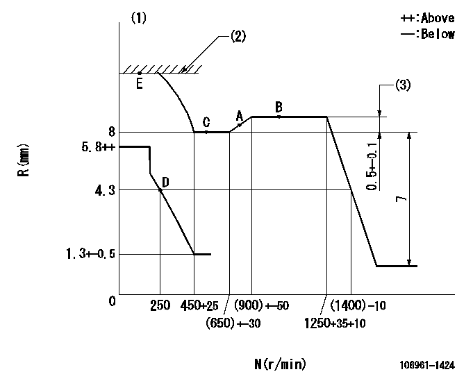
N:Pump speed
R:Rack position (mm)
(1)Damper spring does not operate.
(2)Excess fuel setting for starting: SXL
(3)Rack difference between N = N1 and N = N2
----------
SXL=11+0.2mm N1=1250r/min N2=500r/min
----------
----------
SXL=11+0.2mm N1=1250r/min N2=500r/min
----------
Speed control lever angle

F:Full speed
----------
----------
a=7deg+-5deg
----------
----------
a=7deg+-5deg
0000000901

F:Full load
I:Idle
(1)Stopper bolt setting
----------
----------
a=10deg+-5deg b=36deg+-3deg
----------
----------
a=10deg+-5deg b=36deg+-3deg
Stop lever angle

N:Pump normal
S:Stop the pump.
----------
----------
a=60deg+-5deg b=73deg+-5deg
----------
----------
a=60deg+-5deg b=73deg+-5deg
Timing setting

(1)Pump vertical direction
(2)Position of "Z" mark at the No 1 cylinder's beginning of injection (governor side)
(3)B.T.D.C.: aa
(4)-
----------
aa=16deg
----------
a=(170deg)
----------
aa=16deg
----------
a=(170deg)
Information:
You should follow the instructions in Operations and Maintenance Manual, "Initialization for Direct Connection" before you connect by a modem. The user can verify proper operation of the CCM at the location. The user can also become familiar with the CCM. Make sure that the following equipment is available:
A personal computer with a terminal emulator software program. Examples of terminal emulators include Procomm, PC-VT, or Terminal under the Accessories window in Microsoft Windows. Refer to "Caterpillar CCM PC For Windows: Getting Started Manual" for specifications on the PC. The user is responsible for understanding the operation of the PC.
The proper RS-232C cables are required for the particular installation. An RS-232C cable must be temporarily connected from the PC to the Answering Modem. Refer to Operation and Maintenance Manual, "RS-232C Cable Requirements".
The two modems must support the Hayes AT command set. This is necessary for both the Answering Modem and the Originating Modem.
The CCM PC For Windows software is required. This software is available from Caterpillar.Note: Some personal computers will have an internal modem. The internal modem may be used as the Originating Modem. The internal modem must be compatible with the Answering Modem. Consult the instructions for the two modems.ProcedurePerform the following procedure in order to initialize communication with the CCM and the Answering Modem. The Originating Modem is set up later by the PC software.Note: In the following steps, the PC and the modems should be turned OFF before you change the cables on the serial ports. When power is reapplied, the modem must be powered up first.
The CCM should be installed with all of the wiring. Refer to the Operations and Maintenance Manual, "General Wiring Diagram" and "RS-232C Cable Requirements".
Determine the parameters for communication for the installation. The RS-232C default rate of communication (bits per second or bps) is 9600. The remaining default settings from the factory are no parity, 8 data bits, and 1 stop bit. These parameters will work well in most installations. Use the Operation and Maintenance Manual, "Communication Parameters - Identify" to determine the parameters of communication that are stored in the CCM.Note: The RS-232C serial port communication baud rate is often referred to as the DTE speed. The phone port communication rate is often referred to as the DCE speed.
Connect the RS-232C port of the Answering Modem directly to the RS-232C port of the PC. This connection is temporary. This connection is required to set up the Answering Modem.
Use the terminal emulator on the PC to set the parameters for communication for the RS-232C port. Use the same values that were chosen in step 2.
Several commands must be sent to the Answering Modem that set the parameters for communication to the proper values. The examples in Table 1 are Hayes AT commands. Actual command sets vary widely between modem manufacturers. Consult the manual for the modem. Save these parameters to the modem memory.
Table 1
Typical Answering Modem Setup Commands
Item Explanation Command Example Command