Information injection-pump assembly
ZEXEL
106961-1317
1069611317
ISUZU
1156013945
1156013945
Rating:
Service parts 106961-1317 INJECTION-PUMP ASSEMBLY:
1.
_
6.
COUPLING PLATE
7.
COUPLING PLATE
8.
_
9.
_
11.
Nozzle and Holder
1-15300-138-2
12.
Open Pre:MPa(Kqf/cm2)
15.7{160}/22.1{225}
15.
NOZZLE SET
Include in #1:
106961-1317
as INJECTION-PUMP ASSEMBLY
Cross reference number
ZEXEL
106961-1317
1069611317
ISUZU
1156013945
1156013945
Zexel num
Bosch num
Firm num
Name
Calibration Data:
Adjustment conditions
Test oil
1404 Test oil ISO4113 or {SAEJ967d}
1404 Test oil ISO4113 or {SAEJ967d}
Test oil temperature
degC
40
40
45
Nozzle and nozzle holder
105780-8140
Bosch type code
EF8511/9A
Nozzle
105780-0000
Bosch type code
DN12SD12T
Nozzle holder
105780-2080
Bosch type code
EF8511/9
Opening pressure
MPa
17.2
Opening pressure
kgf/cm2
175
Injection pipe
Outer diameter - inner diameter - length (mm) mm 8-3-600
Outer diameter - inner diameter - length (mm) mm 8-3-600
Overflow valve opening pressure
kPa
157
123
191
Overflow valve opening pressure
kgf/cm2
1.6
1.25
1.95
Tester oil delivery pressure
kPa
157
157
157
Tester oil delivery pressure
kgf/cm2
1.6
1.6
1.6
Direction of rotation (viewed from drive side)
Right R
Right R
Injection timing adjustment
Direction of rotation (viewed from drive side)
Right R
Right R
Injection order
1-4-9-8-
5-2-11-1
0-3-6-7-
Pre-stroke
mm
4
3.97
4.03
Beginning of injection position
Governor side NO.1
Governor side NO.1
Difference between angles 1
Cal 1-4 deg. 15 14.75 15.25
Cal 1-4 deg. 15 14.75 15.25
Difference between angles 2
Cal 1-9 deg. 60 59.75 60.25
Cal 1-9 deg. 60 59.75 60.25
Difference between angles 3
Cal 1-8 deg. 75 74.75 75.25
Cal 1-8 deg. 75 74.75 75.25
Difference between angles 4
Cal 1-5 deg. 120 119.75 120.25
Cal 1-5 deg. 120 119.75 120.25
Difference between angles 5
Cyl.1-2 deg. 135 134.75 135.25
Cyl.1-2 deg. 135 134.75 135.25
Difference between angles 6
Cal 1-11 deg. 180 179.75 180.25
Cal 1-11 deg. 180 179.75 180.25
Difference between angles 7
Cal 1-10 deg. 195 194.75 195.25
Cal 1-10 deg. 195 194.75 195.25
Difference between angles 8
Cal 1-3 deg. 240 239.75 240.25
Cal 1-3 deg. 240 239.75 240.25
Difference between angles 9
Cal 1-6 deg. 255 254.75 255.25
Cal 1-6 deg. 255 254.75 255.25
Difference between angles 10
Cal 1-7 deg. 300 299.75 300.25
Cal 1-7 deg. 300 299.75 300.25
Difference between angles 11
Cal 1-12 deg. 315 314.75 315.25
Cal 1-12 deg. 315 314.75 315.25
Injection quantity adjustment
Adjusting point
A
Rack position
8.5
Pump speed
r/min
750
750
750
Average injection quantity
mm3/st.
89.8
88.3
91.3
Max. variation between cylinders
%
0
-2
2
Basic
*
Fixing the lever
*
Injection quantity adjustment_02
Adjusting point
B
Rack position
8.7
Pump speed
r/min
1000
1000
1000
Average injection quantity
mm3/st.
105.7
103.7
107.7
Max. variation between cylinders
%
0
-3
3
Fixing the lever
*
Injection quantity adjustment_03
Adjusting point
C
Rack position
8.5+-0.5
Pump speed
r/min
1300
1300
1300
Average injection quantity
mm3/st.
108
104
112
Max. variation between cylinders
%
0
-3
3
Fixing the lever
*
Injection quantity adjustment_04
Adjusting point
D
Rack position
6.8+-0.5
Pump speed
r/min
225
225
225
Average injection quantity
mm3/st.
14.5
13.1
15.9
Max. variation between cylinders
%
0
-13
13
Fixing the rack
*
Remarks
Adjust only variation between cylinders; adjust governor according to governor specifications.
Adjust only variation between cylinders; adjust governor according to governor specifications.
Injection quantity adjustment_05
Adjusting point
F
Rack position
-
Pump speed
r/min
150
150
150
Average injection quantity
mm3/st.
135
135
Fixing the lever
*
Remarks
When manual lever is on the boost side
When manual lever is on the boost side
Timer adjustment
Pump speed
r/min
1050+50
Advance angle
deg.
0
0
0
Remarks
Start
Start
Timer adjustment_02
Pump speed
r/min
1350
Advance angle
deg.
7.5
7
8
Remarks
Finish
Finish
Test data Ex:
Governor adjustment
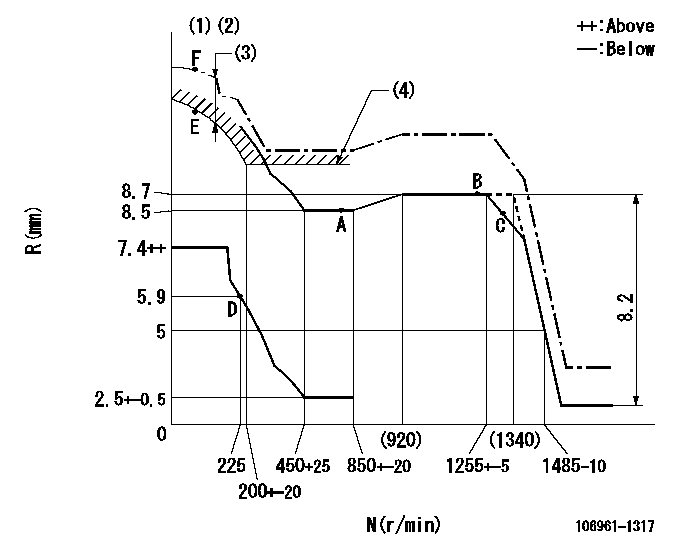
N:Pump speed
R:Rack position (mm)
(1)Supplied with damper spring not set.
(2)Supply solenoid operating voltage DC24V and move the solenoid body so that the excess lever reaches the excess position at the solenoid's maximum stroke.
(3)At excess fuel lever operation: not exceeding EXL
(4)Excess fuel setting for starting: SXL
----------
EXL=1.5mm SXL=10.2+-0.1mm
----------
----------
EXL=1.5mm SXL=10.2+-0.1mm
----------
Speed control lever angle

F:Full speed
----------
----------
a=10deg+-5deg
----------
----------
a=10deg+-5deg
0000000901

F:Full load
I:Idle
(1)Stopper bolt setting
----------
----------
a=10deg+-5deg b=32deg+-3deg
----------
----------
a=10deg+-5deg b=32deg+-3deg
Stop lever angle

N:Pump normal
S:Stop the pump.
----------
----------
a=60deg+-5deg b=73deg+-5deg
----------
----------
a=60deg+-5deg b=73deg+-5deg
0000001101

N:Normal
B:When boosted
----------
----------
a=(5deg) b=24deg
----------
----------
a=(5deg) b=24deg
Timing setting

(1)Pump vertical direction
(2)Position of "Z" mark at the No 1 cylinder's beginning of injection (governor side)
(3)B.T.D.C.: aa
(4)-
----------
aa=13deg
----------
a=(170deg)
----------
aa=13deg
----------
a=(170deg)
Information:
Problem 4
The starting motor remains engaged or the starting motor continues to run after the engine is running.
Check the components of the starting circuit.
Measure the voltages at terminal (TS-26) of the junction box and at terminal (ESS-12) of the electronic speed switch while the engine is running. Result
The voltage at both terminals is zero volts.The problem is in the starting motor (SM), the pinion solenoid (PS), or the magnetic switch (MS). Repair the faulty component. STOP.
The voltage at terminal (ESS-12) is between 15 volts and 32 volts. The voltage at terminal (TS-26) is above 15 volts or below 15 volts but not zero volts.The contacts for the crank terminate (CT) switch of the electronic speed switch (ESS) do not open. Refer to Testing and Adjusting, "Crank Terminate Speed Calibration". If the ESS is not faulty, check diode (D3). Refer to Testing and Adjusting, "Diode Test".
The voltage at both terminals is between 15 volts and 32 volts.The voltage at the terminals is greater than zero volts. During the normal operation of the start/stop switch, the start/stop switch opens across the contacts of the START position. Also, the start/stop switch closes across the contacts of the RUN position. The switch closes when the toggle or the lever of the switch moves from the START position to the RUN position. Repair the switch if the voltage is zero.
The voltage at terminal (ESS-12) is not zero.The CT contacts of the ESS are not opening. Refer to Testing and Adjusting, "Crank Terminate Speed Calibration".Problem 5
The engine shutdown occurs after the engine runs for more than 3 minutes.
Check the overspeed setting on the electronic speed switch (ESS).
Observe the indicator lamp on the ESS.
Reset the air shutoff lever, if equipped. Result
The indicator lamp on the ESS is turned on.Overspeed is indicated as the cause of the engine shutdown. Press the "RESET" button of the ESS. Find the cause of the overspeed. Refer to Testing and Adjusting, "Overspeed Verification Test" and Testing and Adjusting, "Overspeed Calibration". If the overspeed is adjusted properly and the problem persists, check the shielded cable. Only the shield should be connected to terminal 2 on the ESS. STOP.
The indicator lamp is turned off.Go to Step 2.
Check the oil pressure switches.
Connect a jumper between terminals (TS-9) and (TS-14) of the junction box.
Start the engine. Result
The engine starts and the engine runs.The problem is in the oil pressure switches. Go to Step 7 of "Problem 3".
The engine starts but engine shutdown occurs immediately.Go to Step 1 of "Problem 3".
The engine starts and the engine runs but engine shutdown occurs after the engine runs for more than 3 minutes.Go to Step 3.
The engine cranks but the engine does not start.Go to Step 1 of "Problem 1".Note: If the water temperature contactor switch causes overheating go to Step 8 of "Problem 1". If the water temperature contactor switch is not the problem, go to Step 1of "Problem 1".
Check the slave relay (SR1).
Disconnect the jumper from terminals (TS-9) and (TD-14).
Connect a jumper between terminals (TS-14) and