Information injection-pump assembly
ZEXEL
106961-1307
1069611307
ISUZU
1156013975
1156013975
Rating:
Service parts 106961-1307 INJECTION-PUMP ASSEMBLY:
1.
_
6.
COUPLING PLATE
7.
COUPLING PLATE
8.
_
9.
_
11.
Nozzle and Holder
12.
Open Pre:MPa(Kqf/cm2)
15.7(160)/22.1(225)
15.
NOZZLE SET
Include in #1:
106961-1307
as INJECTION-PUMP ASSEMBLY
Cross reference number
ZEXEL
106961-1307
1069611307
ISUZU
1156013975
1156013975
Zexel num
Bosch num
Firm num
Name
Calibration Data:
Adjustment conditions
Test oil
1404 Test oil ISO4113 or {SAEJ967d}
1404 Test oil ISO4113 or {SAEJ967d}
Test oil temperature
degC
40
40
45
Nozzle and nozzle holder
105780-8140
Bosch type code
EF8511/9A
Nozzle
105780-0000
Bosch type code
DN12SD12T
Nozzle holder
105780-2080
Bosch type code
EF8511/9
Opening pressure
MPa
17.2
Opening pressure
kgf/cm2
175
Injection pipe
Outer diameter - inner diameter - length (mm) mm 8-3-600
Outer diameter - inner diameter - length (mm) mm 8-3-600
Overflow valve
132424-0620
Overflow valve opening pressure
kPa
157
123
191
Overflow valve opening pressure
kgf/cm2
1.6
1.25
1.95
Tester oil delivery pressure
kPa
157
157
157
Tester oil delivery pressure
kgf/cm2
1.6
1.6
1.6
Direction of rotation (viewed from drive side)
Right R
Right R
Injection timing adjustment
Direction of rotation (viewed from drive side)
Right R
Right R
Injection order
1-8-7-6-
5-4-3-10
-9-2
Pre-stroke
mm
4.4
4.37
4.43
Beginning of injection position
Governor side NO.1
Governor side NO.1
Difference between angles 1
Cal 1-8 deg. 27 26.75 27.25
Cal 1-8 deg. 27 26.75 27.25
Difference between angles 2
Cal 1-7 deg. 72 71.75 72.25
Cal 1-7 deg. 72 71.75 72.25
Difference between angles 3
Cal 1-6 deg. 99 98.75 99.25
Cal 1-6 deg. 99 98.75 99.25
Difference between angles 4
Cal 1-5 deg. 144 143.75 144.25
Cal 1-5 deg. 144 143.75 144.25
Difference between angles 5
Cal 1-4 deg. 171 170.75 171.25
Cal 1-4 deg. 171 170.75 171.25
Difference between angles 6
Cal 1-3 deg. 216 215.75 216.25
Cal 1-3 deg. 216 215.75 216.25
Difference between angles 7
Cal 1-10 deg. 243 242.75 243.25
Cal 1-10 deg. 243 242.75 243.25
Difference between angles 8
Cal 1-9 deg. 288 287.75 288.25
Cal 1-9 deg. 288 287.75 288.25
Difference between angles 9
Cyl.1-2 deg. 315 314.75 315.25
Cyl.1-2 deg. 315 314.75 315.25
Injection quantity adjustment
Adjusting point
A
Rack position
8.5
Pump speed
r/min
750
750
750
Average injection quantity
mm3/st.
87.2
85.7
88.7
Max. variation between cylinders
%
0
-2
2
Basic
*
Fixing the lever
*
Injection quantity adjustment_02
Adjusting point
B
Rack position
8.7
Pump speed
r/min
1000
1000
1000
Average injection quantity
mm3/st.
102.5
100.5
104.5
Max. variation between cylinders
%
0
-3
3
Fixing the lever
*
Injection quantity adjustment_03
Adjusting point
C
Rack position
8.2+-0.5
Pump speed
r/min
1150
1150
1150
Average injection quantity
mm3/st.
98.5
94.5
102.5
Max. variation between cylinders
%
0
-3
3
Fixing the lever
*
Injection quantity adjustment_04
Adjusting point
D
Rack position
5.9+-0.5
Pump speed
r/min
225
225
225
Average injection quantity
mm3/st.
8.2
6.8
9.6
Max. variation between cylinders
%
0
-13
13
Fixing the rack
*
Injection quantity adjustment_05
Adjusting point
F
Rack position
-
Pump speed
r/min
150
150
150
Average injection quantity
mm3/st.
133
133
Fixing the lever
*
Remarks
When manual lever is on the boost side
When manual lever is on the boost side
Timer adjustment
Pump speed
r/min
900+50
Advance angle
deg.
0
0
0
Remarks
Start
Start
Timer adjustment_02
Pump speed
r/min
1200
Advance angle
deg.
6.5
6
7
Remarks
Finish
Finish
Test data Ex:
Governor adjustment
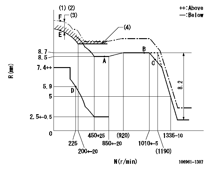
N:Pump speed
R:Rack position (mm)
(1)Supplied with damper spring not set.
(2)Supply solenoid operating voltage DC24V and move the solenoid body so that the excess lever reaches the excess position at the solenoid's maximum stroke.
(3)At excess fuel lever operation: not exceeding EXL
(4)Excess fuel setting for starting: SXL
----------
EXL=1.5mm SXL=10.2+-0.1mm
----------
----------
EXL=1.5mm SXL=10.2+-0.1mm
----------
Speed control lever angle

F:Full speed
----------
----------
a=7deg+-5deg
----------
----------
a=7deg+-5deg
0000000901

F:Full load
I:Idle
(1)Stopper bolt setting
----------
----------
a=10deg+-5deg b=32deg+-3deg
----------
----------
a=10deg+-5deg b=32deg+-3deg
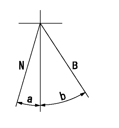
Stop lever angle

N:Pump normal
S:Stop the pump.
----------
----------
a=60deg+-5deg b=73deg+-5deg
----------
----------
a=60deg+-5deg b=73deg+-5deg
0000001101
N:Normal
B:When boosted
----------
----------
a=(5deg) b=(24deg)
----------
----------
a=(5deg) b=(24deg)
Timing setting

(1)Pump vertical direction
(2)Position of "Z" mark at the No 1 cylinder's beginning of injection (governor side)
(3)B.T.D.C.: aa
(4)-
----------
aa=13deg
----------
a=(170deg)
----------
aa=13deg
----------
a=(170deg)
Information:
Illustration 1 g00564355
7W-2743 Electronic Speed Switch (ESS)
(1) Push button for Overspeed Verification
(2) Reset button
(3) Overspeed indicator lamp
(4) Seal screw plug for adjusting the engine overspeed
(5) Seal screw plug for adjusting the crank terminate speed
(6) Seal screw plug for adjusting the oil step pressure speed setting The oil step speed calibration increases the oil step speed setting or the oil step speed calibration decreases the oil step speed setting. Refer to the Speed Specification Chart in order to find the oil step speed that is equal to the engine rpm when the engine is running.
Remove the lockwire and the seal from seal screw plug (6). Remove seal screw plug (6) from the access hole for the oil step speed adjusting screw.
Use a small screwdriver to lightly turn the oil step speed adjusting screw in the direction of the "MAX" arrow or the clockwise direction. Turn the screw twenty times. The oil step speed adjusting screw will vary the setting of a potentiometer that is inside of the ESS. The oil step speed adjusting screw will not cause damage to the potentiometer. Also, the screw can not be removed if the screw is turned in the wrong direction.
Connect a voltmeter with the positive lead at terminal (ESS-13) and the negative lead at (ESS-5). Use a 6V-7070 Digital Multimeter or a voltmeter with the same accuracy. Measure the voltage.
For a specific engine rating, find the engine rpm in the column for the oil step speed setting in the Speed Specification Chart. Run the engine at the rpm that is specified in the table.
While the engine is running, look into the hole for the adjustment of the oil step speed. A red indicator lamp should be lighted. A positive voltage should be observed on the multimeter 9 seconds after the indicator lamp is lighted. Turn the oil step speed adjusting screw clockwise until the indicator lamp turns off. The oil step speed setting is above the present rpm of the engine. Slowly turn the oil step speed adjusting screw counterclockwise until the indicator lamp is lighted. After a 9 second delay, a positive voltage should be observed on the multimeter. This position is the correct setting for the oil step speed.
Install seal screw plug (6) in the access hole for the oil step speed adjusting screw. Tighten the screw to a torque of 0.20 0.03 N m (1.8 .3 lb in). Install the lockwire and the seal if the overspeed calibration and the crank terminate speed calibration are also complete.