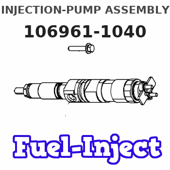
Information injection-pump assembly
ZEXEL
106961-1040
1069611040
ISUZU
1156014561
1156014561
Rating:
Service parts 106961-1040 INJECTION-PUMP ASSEMBLY:
1.
_
6.
COUPLING PLATE
7.
COUPLING PLATE
8.
_
9.
_
11.
Nozzle and Holder
1-15300-138-2
12.
Open Pre:MPa(Kqf/cm2)
15.7{160}/22.1{225}
15.
NOZZLE SET
Include in #1:
106961-1040
as INJECTION-PUMP ASSEMBLY
Cross reference number
ZEXEL
106961-1040
1069611040
ISUZU
1156014561
1156014561
Zexel num
Bosch num
Firm num
Name
Calibration Data:
Adjustment conditions
Test oil
1404 Test oil ISO4113 or {SAEJ967d}
1404 Test oil ISO4113 or {SAEJ967d}
Test oil temperature
degC
40
40
45
Nozzle and nozzle holder
105780-8140
Bosch type code
EF8511/9A
Nozzle
105780-0000
Bosch type code
DN12SD12T
Nozzle holder
105780-2080
Bosch type code
EF8511/9
Opening pressure
MPa
17.2
Opening pressure
kgf/cm2
175
Injection pipe
Outer diameter - inner diameter - length (mm) mm 8-3-600
Outer diameter - inner diameter - length (mm) mm 8-3-600
Overflow valve opening pressure
kPa
157
123
191
Overflow valve opening pressure
kgf/cm2
1.6
1.25
1.95
Tester oil delivery pressure
kPa
157
157
157
Tester oil delivery pressure
kgf/cm2
1.6
1.6
1.6
Direction of rotation (viewed from drive side)
Right R
Right R
Injection timing adjustment
Direction of rotation (viewed from drive side)
Right R
Right R
Injection order
1-8-7-6-
5-4-3-10
-9-2
Pre-stroke
mm
4
3.97
4.03
Beginning of injection position
Governor side NO.1
Governor side NO.1
Difference between angles 1
Cal 1-8 deg. 27 26.75 27.25
Cal 1-8 deg. 27 26.75 27.25
Difference between angles 2
Cal 1-7 deg. 72 71.75 72.25
Cal 1-7 deg. 72 71.75 72.25
Difference between angles 3
Cal 1-6 deg. 99 98.75 99.25
Cal 1-6 deg. 99 98.75 99.25
Difference between angles 4
Cal 1-5 deg. 144 143.75 144.25
Cal 1-5 deg. 144 143.75 144.25
Difference between angles 5
Cal 1-4 deg. 171 170.75 171.25
Cal 1-4 deg. 171 170.75 171.25
Difference between angles 6
Cal 1-3 deg. 216 215.75 216.25
Cal 1-3 deg. 216 215.75 216.25
Difference between angles 7
Cal 1-10 deg. 243 242.75 243.25
Cal 1-10 deg. 243 242.75 243.25
Difference between angles 8
Cal 1-9 deg. 288 287.75 288.25
Cal 1-9 deg. 288 287.75 288.25
Difference between angles 9
Cyl.1-2 deg. 315 314.75 315.25
Cyl.1-2 deg. 315 314.75 315.25
Injection quantity adjustment
Adjusting point
A
Rack position
8.5
Pump speed
r/min
750
750
750
Average injection quantity
mm3/st.
89.8
88.3
91.3
Max. variation between cylinders
%
0
-2
2
Basic
*
Fixing the lever
*
Injection quantity adjustment_02
Adjusting point
B
Rack position
8.7
Pump speed
r/min
1000
1000
1000
Average injection quantity
mm3/st.
105.7
103.7
107.7
Max. variation between cylinders
%
0
-3
3
Fixing the lever
*
Injection quantity adjustment_03
Adjusting point
C
Rack position
8.5+-0.5
Pump speed
r/min
1300
1300
1300
Average injection quantity
mm3/st.
108
104
112
Max. variation between cylinders
%
0
-3
3
Fixing the lever
*
Injection quantity adjustment_04
Adjusting point
D
Rack position
6.8+-0.5
Pump speed
r/min
225
225
225
Average injection quantity
mm3/st.
14.5
13.1
15.9
Max. variation between cylinders
%
0
-13
13
Fixing the rack
*
Remarks
Adjust only variation between cylinders; adjust governor according to governor specifications.
Adjust only variation between cylinders; adjust governor according to governor specifications.
Injection quantity adjustment_05
Adjusting point
F
Rack position
-
Pump speed
r/min
150
150
150
Average injection quantity
mm3/st.
135
135
Fixing the lever
*
Remarks
When manual lever is on the boost side
When manual lever is on the boost side
Test data Ex:
Governor adjustment
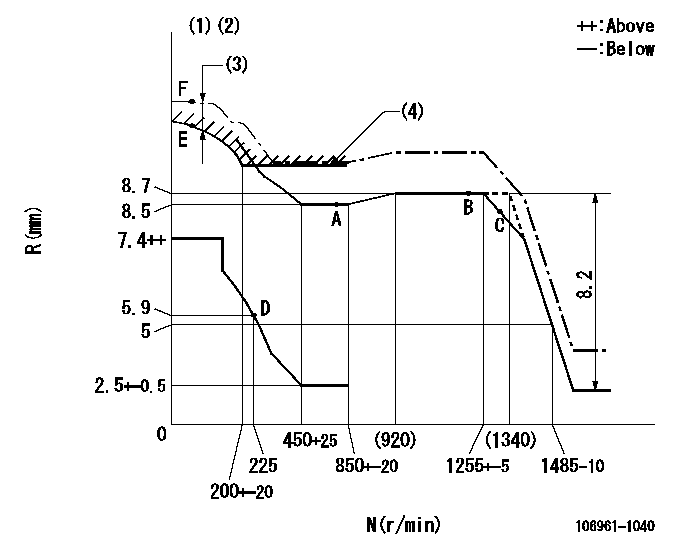
N:Pump speed
R:Rack position (mm)
(1)Supply solenoid operating voltage DC24V and move the solenoid body so that the excess lever reaches the excess position at the solenoid's maximum stroke.
(2)Supplied with damper spring not set.
(3)At excess fuel lever operation: not exceeding EXL
(4)Excess fuel setting for starting: SXL
----------
EXL=1.5mm SXL=10.2+-0.1mm
----------
----------
EXL=1.5mm SXL=10.2+-0.1mm
----------
Timer adjustment

(1)Adjusting range
(2)Step response time
(N): Speed of the pump
(L): Load
(theta) Advance angle
(Srd1) Step response time 1
(Srd2) Step response time 2
1. Adjusting conditions for the variable timer
(1)Adjust the clearance between the pickup and the protrusion to L.
----------
L=1-0.2mm N2=800r/min C2=(7.5)deg t1=1.5--sec. t2=1.5--sec.
----------
N1=1100++r/min P1=0kPa(0kgf/cm2) P2=392kPa(4kgf/cm2) C1=7.5+-0.3deg R01=0/4load R02=4/4load
----------
L=1-0.2mm N2=800r/min C2=(7.5)deg t1=1.5--sec. t2=1.5--sec.
----------
N1=1100++r/min P1=0kPa(0kgf/cm2) P2=392kPa(4kgf/cm2) C1=7.5+-0.3deg R01=0/4load R02=4/4load
Speed control lever angle

F:Full speed
----------
----------
a=10deg+-5deg
----------
----------
a=10deg+-5deg
0000000901

F:Full load
I:Idle
(1)Stopper bolt setting
----------
----------
a=10deg+-5deg b=32deg+-3deg
----------
----------
a=10deg+-5deg b=32deg+-3deg
Stop lever angle

N:Pump normal
S:Stop the pump.
----------
----------
a=36deg+-5deg b=73deg+-3deg
----------
----------
a=36deg+-5deg b=73deg+-3deg
0000001101

N:Normal
B:When boosted
----------
----------
a=(5deg) b=(24deg)
----------
----------
a=(5deg) b=(24deg)
Timing setting

(1)Pump vertical direction
(2)Position of "Z" mark at the No 1 cylinder's beginning of injection (governor side)
(3)B.T.D.C.: aa
(4)-
----------
aa=13deg
----------
a=(170deg)
----------
aa=13deg
----------
a=(170deg)
Information:
PROBLEM
On certain C175-16 and C175-20 Generator Sets the 276-1242 4 pin connector that connects the engine harness to the individual cylinder injector harnesses may not be fully latched do to a damaged connector locking tab.
AFFECTED PRODUCT
Model Identification Number
C175-16 WYB00649-00652, 656, 664-665, 1231-1232, 1237, 1241, 1243, 1249, 1253-1254, 1413, 1417, 1424, 1426, 1431, 1434, 1436, 1438, 1476, 1478-1484, 1508, 1564, 1566, 1569-1570, 1573-1574, 1578, 1610, 1612, 1614, 1622, 1625, 1627, 1630, 1825-1826, 1840-1841, 1846-1853, 1857-1860, 1862-1863, 1869-1871, 1873, 1876-1878, 1885, 1888-1891, 1895, 1899, 1904-1909, 1911, 1914-1920, 1925-1927, 1929, 1931-1932, 1936-1940, 1954, 1956, 1958, 2075, 2084, 2087-2088, 2091-2092, 2095-2096, 2098, 2100-2105, 2108-2109, 2112-2113, 2115-2116, 2118, 2127-2129, 2136-2142, 2179, 2182-2185, 2189, 2192-2193, 2195-2196, 2198, 2200, 2203, 2206-2209, 2214, 2227, 2229, 2232-2233, 2244, 2246, 2248-2257, 2332, 2337, 2342, 2352-2353, 2355-2356, 2359, 2362-2364, 2370-2371, 2416, 2437, 2470, 2475, 2479, 2481, 2493, 2500
C175-20 BXR01781, 1798-1807, 1809, 1826, 1828, 1944-1950, 1953-1956, 1959-1960, 1962, 2013-2014, 2026-2027, 2029, 2036, 2042-2046, 2048-2050, 2055-2058
PARTS NEEDED
Qty
Part Number Description
1 4C6389 TUBING-HEAT SHRI
1 1134630 RECEPTACLE AS
1 2300940 SEAL-PIP
1 2761242 KIT-PLUG CONN
In order to allow equitable parts availability to all participating dealers, please limit your initial parts order to not exceed 1% of dealership population. This is an initial order recommendation only, and the ultimate responsibility for ordering the total number of parts needed to satisfy the program lies with the dealer.
ACTION REQUIRED
1. Inspect 276-1242 4 pin engine harness connector and check the connector locking tab for proper engagement with injector harness receptacle. Image 1 is a damaged locking tab. Image 2 is a good locking tab. If locking tab is found to be damage proceed with replacement.
2. Disconnect the 276-1242 4 pin engine harness connector from the 113-4630 injector harness receptacle at the cylinder head.
3. Remove and replace 276-1242 4 pin connector with new. Insure to reinstall 4C-6389 heat shrink on the connector.
4. Inspect the inside of 113-4630 injector harness receptacle mounted on cylinder head for debris, damage, or paint. If debris, damage, or paint is present, remove and replace 113-4630 injector harness receptacle with new.
Note: Always use a new valve cover gasket if removal of valve cover is required.
5. Reconnect new 276-1242 4 pin engine harness connector to the new 113-4630 injector harnesses receptacle. Insure the connector is fully seated, audible click is heard, lock tab in the proper position, and connector cannot be pulled out.
Image1
Image2
SERVICE CLAIM ALLOWANCES
Product smu/age whichever comes first Caterpillar Dealer Suggested Customer Suggested
Parts % Labor Hrs% Parts % Labor Hrs% Parts % Labor Hrs%
0-600 hrs,
0-45 mo 100.0% 100.0% 0.0% 0.0% 0.0% 0.0%
This is a 1.0-hour job
PARTS DISPOSITION
Handle the parts in accordance with your Warranty Bulletin on warranty parts handling.