Information injection-pump assembly
ZEXEL
106961-0380
1069610380
Rating:
Service parts 106961-0380 INJECTION-PUMP ASSEMBLY:
1.
_
6.
COUPLING PLATE
7.
COUPLING PLATE
8.
_
9.
_
11.
Nozzle and Holder
12.
Open Pre:MPa(Kqf/cm2)
19.6(200)

15.
NOZZLE SET
Include in #1:
106961-0380
as INJECTION-PUMP ASSEMBLY
Cross reference number
ZEXEL
106961-0380
1069610380
Zexel num
Bosch num
Firm num
Name
106961-0380
INJECTION-PUMP ASSEMBLY
Calibration Data:
Adjustment conditions
Test oil
1404 Test oil ISO4113 or {SAEJ967d}
1404 Test oil ISO4113 or {SAEJ967d}
Test oil temperature
degC
40
40
45
Nozzle and nozzle holder
105780-8140
Bosch type code
EF8511/9A
Nozzle
105780-0000
Bosch type code
DN12SD12T
Nozzle holder
105780-2080
Bosch type code
EF8511/9
Opening pressure
MPa
17.2
Opening pressure
kgf/cm2
175
Injection pipe
Outer diameter - inner diameter - length (mm) mm 8-3-600
Outer diameter - inner diameter - length (mm) mm 8-3-600
Overflow valve opening pressure
kPa
157
123
191
Overflow valve opening pressure
kgf/cm2
1.6
1.25
1.95
Tester oil delivery pressure
kPa
157
157
157
Tester oil delivery pressure
kgf/cm2
1.6
1.6
1.6
Direction of rotation (viewed from drive side)
Right R
Right R
Injection timing adjustment
Direction of rotation (viewed from drive side)
Right R
Right R
Injection order
10-9-4-3
-6-5-8-7
-2-1
Pre-stroke
mm
3.65
3.6
3.7
Beginning of injection position
Governor side NO.1
Governor side NO.1
Difference between angles 1
Cal 10-9 deg. 45 44.5 45.5
Cal 10-9 deg. 45 44.5 45.5
Difference between angles 2
Cal 10-4 deg. 72 71.5 72.5
Cal 10-4 deg. 72 71.5 72.5
Difference between angles 3
Cal 10-3 deg. 117 116.5 117.5
Cal 10-3 deg. 117 116.5 117.5
Difference between angles 4
Cal 10-6 deg. 144 143.5 144.5
Cal 10-6 deg. 144 143.5 144.5
Difference between angles 5
Cal 10-5 deg. 189 188.5 189.5
Cal 10-5 deg. 189 188.5 189.5
Difference between angles 6
Cal 10-8 deg. 216 215.5 216.5
Cal 10-8 deg. 216 215.5 216.5
Difference between angles 7
Cal 10-7 deg. 261 260.5 261.5
Cal 10-7 deg. 261 260.5 261.5
Difference between angles 8
Cal 10-2 deg. 288 287.5 288.5
Cal 10-2 deg. 288 287.5 288.5
Difference between angles 9
Cal 10-1 deg. 333 332.5 333.5
Cal 10-1 deg. 333 332.5 333.5
Injection quantity adjustment
Adjusting point
A
Rack position
9.1
Pump speed
r/min
750
750
750
Average injection quantity
mm3/st.
115
113
117
Max. variation between cylinders
%
0
-4
4
Basic
*
Fixing the lever
*
Injection quantity adjustment_02
Adjusting point
B
Rack position
8.1
Pump speed
r/min
750
750
750
Average injection quantity
mm3/st.
95
93
97
Max. variation between cylinders
%
0
-4
4
Fixing the rack
*
Injection quantity adjustment_03
Adjusting point
C
Rack position
5.3+-0.5
Pump speed
r/min
300
300
300
Average injection quantity
mm3/st.
14
12
16
Max. variation between cylinders
%
0
-10
10
Fixing the rack
*
Timer adjustment
Pump speed
r/min
300+10
Advance angle
deg.
0
0
0
Remarks
Start
Start
Timer adjustment_02
Pump speed
r/min
700
Advance angle
deg.
3
2.5
3.5
Timer adjustment_03
Pump speed
r/min
900
Advance angle
deg.
4.7
4.2
5.2
Timer adjustment_04
Pump speed
r/min
-
Advance angle
deg.
8
8
8
Remarks
Measure the actual speed, stop
Measure the actual speed, stop
Test data Ex:
Governor adjustment
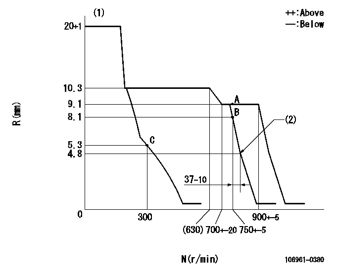
N:Pump speed
R:Rack position (mm)
(1)Target notch: K
(2)Idle sub spring setting: L1.
----------
K=7 L1=4.8-0.1mm
----------
----------
K=7 L1=4.8-0.1mm
----------
Speed control lever angle
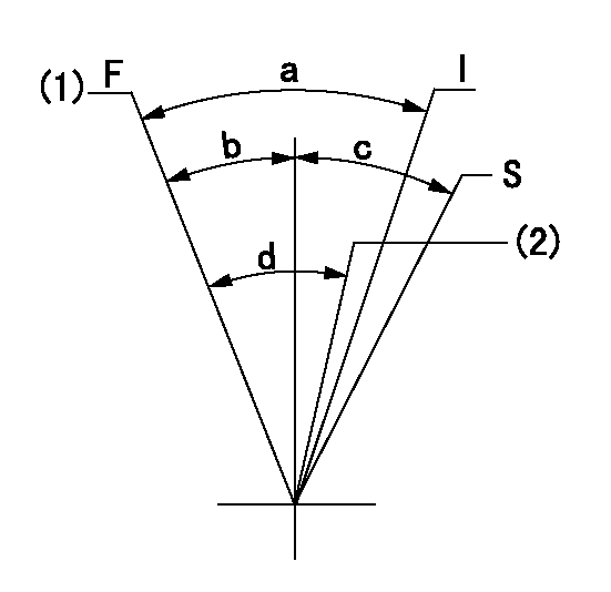
F:Full speed
I:Idle
S:Stop
(1)Speed set at aa (setting at shipping)
(2)Set the pump speed at bb.
----------
aa=900r/min bb=750r/min
----------
a=(23deg)+-5deg b=(3deg)+-5deg c=32deg+-3deg d=(6deg)+-5deg
----------
aa=900r/min bb=750r/min
----------
a=(23deg)+-5deg b=(3deg)+-5deg c=32deg+-3deg d=(6deg)+-5deg
Stop lever angle

N:Pump normal
S:Stop the pump.
----------
----------
a=26deg+-5deg b=53deg+-5deg
----------
----------
a=26deg+-5deg b=53deg+-5deg
0000001501 GOV FULL LOAD ADJUSTMENT
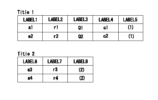
Title1:Full load stopper adjustment
Title2:Governor set speed
LABEL1:Distinguishing
LABEL2:Pump speed (r/min)
LABEL3:Ave. injection quantity (mm3/st)
LABEL4:Max. var. bet. cyl.
LABEL5:Remarks
LABEL6:Distinguishing
LABEL7:Governor set speed (r/min)
LABEL8:Remarks
(1)Adjustment conditions are the same as those for measuring injection quantity.
(2)-
----------
----------
a1=A a2=E r1=750r/min r2=750r/min Q1=115+-2mm3/st Q2=- c1=+-4% c2=+-4% a3=18 a4=15 r3=900r/min r4=750r/min
----------
----------
a1=A a2=E r1=750r/min r2=750r/min Q1=115+-2mm3/st Q2=- c1=+-4% c2=+-4% a3=18 a4=15 r3=900r/min r4=750r/min
Information:
25Sep2017
U-495
A-349
D-407
O-412
Parts stock action only
PRODUCT IMPROVEMENT PROGRAM FOR INSPECTING AND POSSIBLY REPLACING AN O-RING SEAL ON CERTAIN HEUI REMAN FUEL INJECTORS IN DEALER PARTS STOCK
7750 1290 PI70680
Caterpillar’s obligations under this Service Letter are subject to, and shall not apply in contravention of, the laws, rules, regulations, directives, ordinances, orders, or statutes of the United States, or of any other applicable jurisdiction, without recourse or liability with respect to Caterpillar.
When submitting claim for Parts Stock Action, Use the appropriate 99Z as the s/n, the appropriate Service Letter Program Number as the Part number in the Part Causing Failure field, "7751" as the Group Number, "56" as the Description Code.
The information supplied in this service letter may not be valid after the termination date of this program.Do not perform the work outlined in this Service Letter after the termination date without first contacting your Caterpillar product analyst.
TERMINATION DATE
31Dec2017
PROBLEM
An incorrect O-ring seal may possibly be included with certain HEUI Reman Fuel Injectors. If the incorrect O-ring seal is installed in an engine, it can cause excessive smoke, oil mixed with fuel, and/or misfire.
ACTION REQUIRED
Inspect the following injector part numbers in dealer parts stock:
0R1050
0R9348
0R9349
0R9350
10R0781
10R0782
10R1257
10R1262
10R1306
10R8999
10R9237
10R9238
10R9239
The incorrect O-ring seal will have a larger in inner diameter and will be not as thick as the 148-2903 O-Ring Seal. The incorrect O-ring seal will be loose on the nozzle case when installed on a fuel injector (Image 1).
The O-ring seals are shipped in a injector seal kit that is included with each injector (Image 2).
Using a 148-2903 O-Ring Seal, compare the injector seal kit to identify if there an incorrect seal. If there is an incorrect seal, replace the incorrect seal with a 148-2903 O-Ring Seal (Image 3).
Once inspected, mark the injector's packaging that it was inspected per this program and return the part to dealer parts stock.
Image1
Image2
Image3
SERVICE CLAIM ALLOWANCES
Submit one claim for all parts inspected and reworked in dealer part stock. 5 minutes will be allowed to inspect each injector and 5 minutes will be allowed to replace incorrect O-Ring. One 148-2903 O-ring per reworked injector will be allowed. Include total amount of injectors inspected or reworked. For each injector that was reworked, include injector serial number.
PARTS DISPOSITION
Handle the parts in accordance with your Warranty Bulletin on warranty parts handling.
Have questions with 106961-0380?
Group cross 106961-0380 ZEXEL
Nissan-Diesel
Nissan-Diesel
Nissan-Diesel
106961-0380
INJECTION-PUMP ASSEMBLY