Information injection-pump assembly
BOSCH
9 400 618 572
9400618572
ZEXEL
106961-0242
1069610242
NISSAN-DIESEL
1670097018
1670097018

Rating:
Service parts 106961-0242 INJECTION-PUMP ASSEMBLY:
1.
_
7.
COUPLING PLATE
8.
_
9.
_
11.
Nozzle and Holder
1660097012
12.
Open Pre:MPa(Kqf/cm2)
19.6(200)
15.
NOZZLE SET
Include in #1:
106961-0242
as INJECTION-PUMP ASSEMBLY
Cross reference number
BOSCH
9 400 618 572
9400618572
ZEXEL
106961-0242
1069610242
NISSAN-DIESEL
1670097018
1670097018
Zexel num
Bosch num
Firm num
Name
106961-0242
9 400 618 572
1670097018 NISSAN-DIESEL
INJECTION-PUMP ASSEMBLY
RD10 * K
RD10 * K
Calibration Data:
Adjustment conditions
Test oil
1404 Test oil ISO4113 or {SAEJ967d}
1404 Test oil ISO4113 or {SAEJ967d}
Test oil temperature
degC
40
40
45
Nozzle and nozzle holder
105780-8140
Bosch type code
EF8511/9A
Nozzle
105780-0000
Bosch type code
DN12SD12T
Nozzle holder
105780-2080
Bosch type code
EF8511/9
Opening pressure
MPa
17.2
Opening pressure
kgf/cm2
175
Injection pipe
Outer diameter - inner diameter - length (mm) mm 8-3-600
Outer diameter - inner diameter - length (mm) mm 8-3-600
Tester oil delivery pressure
kPa
157
157
157
Tester oil delivery pressure
kgf/cm2
1.6
1.6
1.6
Direction of rotation (viewed from drive side)
Right R
Right R
Injection timing adjustment
Direction of rotation (viewed from drive side)
Right R
Right R
Injection order
10-9-4-3
-6-5-8-7
-2-1
Pre-stroke
mm
3.65
3.6
3.7
Beginning of injection position
Governor side NO.1
Governor side NO.1
Difference between angles 1
Cal 10-9 deg. 45 44.5 45.5
Cal 10-9 deg. 45 44.5 45.5
Difference between angles 2
Cal 10-4 deg. 72 71.5 72.5
Cal 10-4 deg. 72 71.5 72.5
Difference between angles 3
Cal 10-3 deg. 117 116.5 117.5
Cal 10-3 deg. 117 116.5 117.5
Difference between angles 4
Cal 10-6 deg. 144 143.5 144.5
Cal 10-6 deg. 144 143.5 144.5
Difference between angles 5
Cal 10-5 deg. 189 188.5 189.5
Cal 10-5 deg. 189 188.5 189.5
Difference between angles 6
Cal 10-8 deg. 216 215.5 216.5
Cal 10-8 deg. 216 215.5 216.5
Difference between angles 7
Cal 10-7 deg. 261 260.5 261.5
Cal 10-7 deg. 261 260.5 261.5
Difference between angles 8
Cal 10-2 deg. 288 287.5 288.5
Cal 10-2 deg. 288 287.5 288.5
Difference between angles 9
Cal 10-1 deg. 333 332.5 333.5
Cal 10-1 deg. 333 332.5 333.5
Injection quantity adjustment
Adjusting point
A
Rack position
11.5
Pump speed
r/min
700
700
700
Average injection quantity
mm3/st.
109
108
110
Max. variation between cylinders
%
0
-4
4
Basic
*
Fixing the lever
*
Remarks
Rack limit using stop lever.
Rack limit using stop lever.
Injection quantity adjustment_02
Adjusting point
B
Rack position
11.5
Pump speed
r/min
1000
1000
1000
Average injection quantity
mm3/st.
107
104
110
Max. variation between cylinders
%
0
-4
4
Fixing the lever
*
Injection quantity adjustment_03
Adjusting point
C
Rack position
11.5
Pump speed
r/min
1200
1200
1200
Average injection quantity
mm3/st.
112
108
116
Max. variation between cylinders
%
0
-4
4
Fixing the lever
*
Injection quantity adjustment_04
Adjusting point
D
Rack position
5.6+-0.5
Pump speed
r/min
250
250
250
Average injection quantity
mm3/st.
18.6
16.6
20.6
Max. variation between cylinders
%
0
-10
10
Fixing the rack
*
Remarks
Adjust only variation between cylinders; adjust governor according to governor specifications.
Adjust only variation between cylinders; adjust governor according to governor specifications.
Timer adjustment
Pump speed
r/min
600
Advance angle
deg.
0.5
Timer adjustment_02
Pump speed
r/min
750
Advance angle
deg.
0.8
Timer adjustment_03
Pump speed
r/min
1000
Advance angle
deg.
1.7
1.2
2.2
Timer adjustment_04
Pump speed
r/min
1250+-25
Advance angle
deg.
4
3.3
4.5
Remarks
Finish
Finish
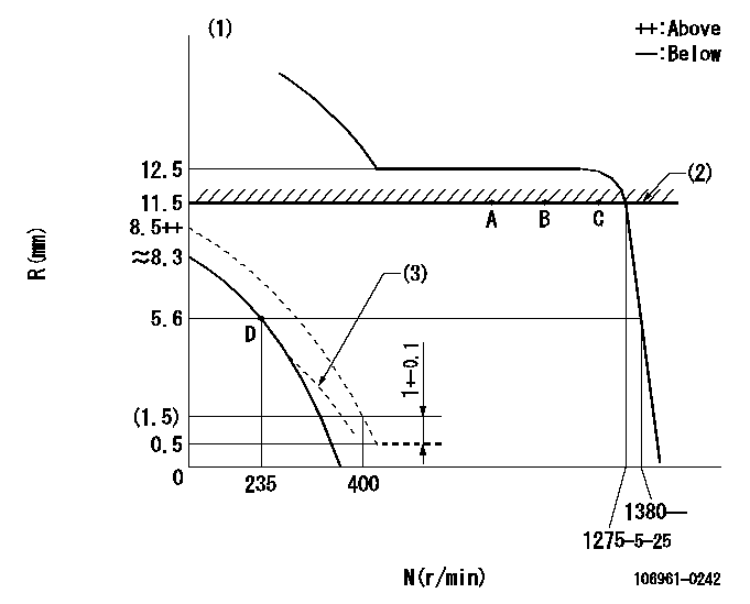
Test data Ex:
Governor adjustment

N:Pump speed
R:Rack position (mm)
(1)After completing adjustment of the broken line, set the lever at the unbroken line position.
(2)Rack limit using stop lever
(3)Beginning of damper spring operation: DL
----------
DL=5.1-0.5mm
----------
----------
DL=5.1-0.5mm
----------
0000000901

F:Full load
I:Idle
(1)Stopper bolt setting
----------
----------
a=13deg+-5deg b=23deg+-3deg
----------
----------
a=13deg+-5deg b=23deg+-3deg
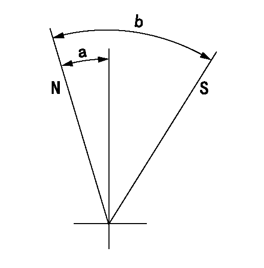
Stop lever angle

N:Pump normal
S:Stop the pump.
----------
----------
a=14deg+-5deg b=32deg+-3deg
----------
----------
a=14deg+-5deg b=32deg+-3deg
Information:
Example of Pulse Width ModulationRated Fuel Position("Rated Fuel Pos" on ECAP) - this indicates the maximum allowable fuel position (longest injection pulse). It will produce rated power for this engine configuration.Reference VoltageA regulated, unchanging voltage supplied by the ECM to a sensor. The reference voltage is used by the sensor to generate a signal voltage. Remote Station OperationEngine speed control from a location outside of the vehicle cab, typically for some type of PTO operation for pumping or other application using engine power.SensorA device used to detect and convert a change in pressure, temperature, or mechanical movement into an electrical signal.Service Brake SwitchThis OEM supplied and installed switch is typically a pressure switch. This switch is normally closed with the pedal released. Depressing the brake will open the circuit.Service Engine Soon LampSometimes referred to as the "Diagnostic Lamp", it is used to alert the operator of the presence of an active event and is used to flash a diagnostic code.Service Program Module (SPM)A software program on a factory programmable computer chip, designed to adapt an Electronic Service Tool to a specific application.Short CircuitA condition where an electrical circuit is unintentionally connected to an undesirable point. Example: a wire which rubs against a vehicle frame until it wears off its insulation and makes electrical contact with the frame.SignalA voltage or waveform used to transmit information typically from a sensor to the ECM.Speed "burp"A sudden, brief, unwanted change in engine rpm.Speed/Timing SensorA sensor that measures crankshaft position, direction of rotation and engine rpm and sends signal to ECM.Standard SAE Diagnostic Communications Data LinkRefer to ATA Data Link.SubsystemAs used here, it is a part of the Electronic System that relates to a particular function, for instance throttle subsystem, etc.Supply VoltageA constant voltage supplied to a component to provide electrical power for its operation. It may be generated by the ECM, or it may be vehicle battery voltage supplied by the vehicle wiring.System Configuration ParametersParameters which affect power rating family or emissions."T" HarnessA test harness designed to connect into vehicle or engine harness which allows normal circuit operation while providing a breakout or "T" to measure signals.Throttle PositionThe ECM interpretation of the signal from the Throttle Position Sensor.Throttle Position SensorAn electronic sensor which is connected to the accelerator pedal and sends a Pulse Width Modulated Signal to the ECM.Timing CalibrationThe adjustment of an electrical signal as a means of correcting timing error between the crankshaft and camshaft. Refer to Speed/Timing Sensor.Torque LimitProgrammable parameter which limits the maximum torque based on PTO Configuration and operation.Total TattletaleTotal number of changes to all Customer Specified Parameters stored in the ECM.Transmission StyleProgrammable parameter that designates the type of transmission in the vehicle and the circuits connected to the ECM. The transmission relay, cruise control, idle/PTO, and exhaust brake operation are affected by this parameter setting.Trip RecorderAn after market device dedicated to recording vehicle and engine operating parameters during vehicle service. Used to analyze driving habits and produce driver logs.Vehicle Speed CalibrationProgrammable parameter used by the ECM
Have questions with 106961-0242?
Group cross 106961-0242 ZEXEL
Nissan-Diesel
Nissan-Diesel
Nissan-Diesel
Nissan-Diesel
Nissan-Diesel
Nissan-Diesel
106961-0242
9 400 618 572
1670097018
INJECTION-PUMP ASSEMBLY
RD10
RD10