Information injection-pump assembly
BOSCH
9 400 618 571
9400618571
ZEXEL
106961-0234
1069610234
NISSAN-DIESEL
1671397017
1671397017
Rating:
Cross reference number
BOSCH
9 400 618 571
9400618571
ZEXEL
106961-0234
1069610234
NISSAN-DIESEL
1671397017
1671397017
Zexel num
Bosch num
Firm num
Name
106961-0234
9 400 618 571
1671397017 NISSAN-DIESEL
INJECTION-PUMP ASSEMBLY
RD10 * K
RD10 * K
Calibration Data:
Adjustment conditions
Test oil
1404 Test oil ISO4113 or {SAEJ967d}
1404 Test oil ISO4113 or {SAEJ967d}
Test oil temperature
degC
40
40
45
Nozzle and nozzle holder
105780-8140
Bosch type code
EF8511/9A
Nozzle
105780-0000
Bosch type code
DN12SD12T
Nozzle holder
105780-2080
Bosch type code
EF8511/9
Opening pressure
MPa
17.2
Opening pressure
kgf/cm2
175
Injection pipe
Outer diameter - inner diameter - length (mm) mm 8-3-600
Outer diameter - inner diameter - length (mm) mm 8-3-600
Overflow valve opening pressure
kPa
157
123
191
Overflow valve opening pressure
kgf/cm2
1.6
1.25
1.95
Tester oil delivery pressure
kPa
157
157
157
Tester oil delivery pressure
kgf/cm2
1.6
1.6
1.6
Direction of rotation (viewed from drive side)
Right R
Right R
Injection timing adjustment
Direction of rotation (viewed from drive side)
Right R
Right R
Injection order
10-9-4-3
-6-5-8-7
-2-1
Pre-stroke
mm
3.65
3.6
3.7
Beginning of injection position
Governor side NO.1
Governor side NO.1
Difference between angles 1
Cal 10-9 deg. 45 44.5 45.5
Cal 10-9 deg. 45 44.5 45.5
Difference between angles 2
Cal 10-4 deg. 72 71.5 72.5
Cal 10-4 deg. 72 71.5 72.5
Difference between angles 3
Cal 10-3 deg. 117 116.5 117.5
Cal 10-3 deg. 117 116.5 117.5
Difference between angles 4
Cal 10-6 deg. 144 143.5 144.5
Cal 10-6 deg. 144 143.5 144.5
Difference between angles 5
Cal 10-5 deg. 189 188.5 189.5
Cal 10-5 deg. 189 188.5 189.5
Difference between angles 6
Cal 10-8 deg. 216 215.5 216.5
Cal 10-8 deg. 216 215.5 216.5
Difference between angles 7
Cal 10-7 deg. 261 260.5 261.5
Cal 10-7 deg. 261 260.5 261.5
Difference between angles 8
Cal 10-2 deg. 288 287.5 288.5
Cal 10-2 deg. 288 287.5 288.5
Difference between angles 9
Cal 10-1 deg. 333 332.5 333.5
Cal 10-1 deg. 333 332.5 333.5
Injection quantity adjustment
Adjusting point
A
Rack position
11.5
Pump speed
r/min
700
700
700
Average injection quantity
mm3/st.
109
108
110
Max. variation between cylinders
%
0
-4
4
Basic
*
Fixing the lever
*
Injection quantity adjustment_02
Adjusting point
B
Rack position
11.5
Pump speed
r/min
1200
1200
1200
Average injection quantity
mm3/st.
112
108
116
Max. variation between cylinders
%
0
-4
4
Fixing the lever
*
Injection quantity adjustment_03
Adjusting point
C
Rack position
5.7+-0.5
Pump speed
r/min
250
250
250
Average injection quantity
mm3/st.
18.6
16.6
20.6
Max. variation between cylinders
%
0
-10
10
Fixing the rack
*
Timer adjustment
Pump speed
r/min
600
Advance angle
deg.
0.5
Timer adjustment_02
Pump speed
r/min
750
Advance angle
deg.
0.8
Timer adjustment_03
Pump speed
r/min
1000
Advance angle
deg.
1.7
1.2
2.2
Timer adjustment_04
Pump speed
r/min
1250+-25
Advance angle
deg.
4
3.3
4.5
Remarks
Finish
Finish
Test data Ex:
Governor adjustment
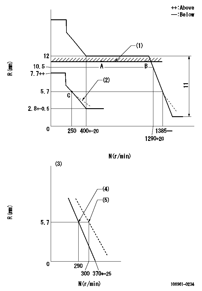
N:Pump speed
R:Rack position (mm)
(1)Rack limit using the stop lever: R1
(2)Damper spring setting: DL
(3)Variable speed specification: idling adjustment
(4)Main spring setting
(5)Set idle sub-spring
----------
R1=11.5mm DL=5.4-0.2mm
----------
----------
R1=11.5mm DL=5.4-0.2mm
----------
Speed control lever angle
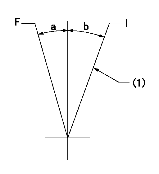
F:Full speed
I:Idle
(1)Stopper bolt setting
----------
----------
a=15deg+-5deg b=10deg+-5deg
----------
----------
a=15deg+-5deg b=10deg+-5deg
0000000901
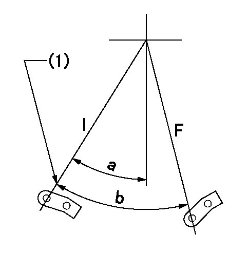
F:Full load
I:Idle
(1)Stopper bolt setting
----------
----------
a=24.5deg+-5deg b=34deg+-3deg
----------
----------
a=24.5deg+-5deg b=34deg+-3deg
Stop lever angle
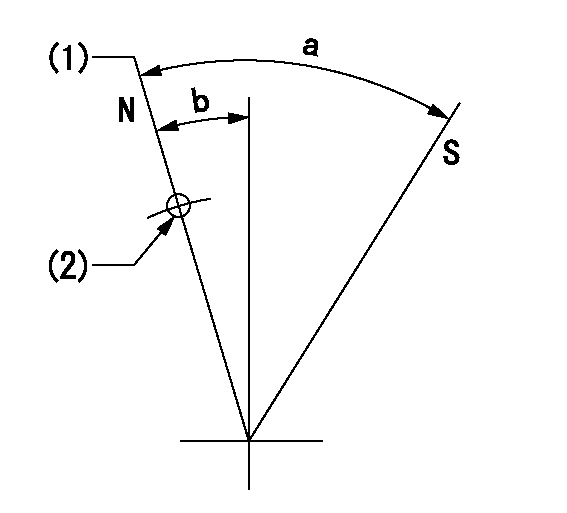
N:Pump normal
S:Stop the pump.
(1)Rack position = aa
(2)Use the hole at R = bb
----------
aa=11.5mm bb=32mm
----------
a=29.5deg+-5deg b=4deg+-5deg
----------
aa=11.5mm bb=32mm
----------
a=29.5deg+-5deg b=4deg+-5deg
Information:
Programming a Personality Module Using Flash Programming
Operation of the engine following programming of the Personality Module is identical to operation following replacement of the Personality Module chip. The only difference is the software was already programmed into the chip for you when you replaced the chip. Now you are actually performing the programming function. For example, if rerating an engine, there is still a need for Factory Passwords to change the Personality Module Code.1. Connect components as shown below. 2. Start the LEXT3037 PC Program.3. Select the engine Personality Module part number to be programmed into the ECM, and proceed with programming the Personality Module. A new ECM is shipped with a blank Personality Module.4. PC Program Personality Module Messages and Their Meaning. A new ECM comes with a blank (previously unprogrammed) personality module. A blank personality module will prompt you for all three of the following messages. The information contained in the "ECM Status" will be scrambled and meaningless if the module has not been previously programmed (this is normal).- Message - "The engine ID in the flash file does not match the engine ID in the ECM."- Meaning - The ECM has a personality module for a different engine. For example, the ECM has a 3116 personality module, and you are attempting to program a 3126 personality module.- What you should do. Stop the transfer and access information about "ECM Status" under the "Electronic Control Module" menu. Ensure the file you are about to transfer is for the same engine it will be installed.- Message- "The application ID in the flash file does not match the application ID in the ECM."- Meaning- The ECM has a personality module for a different application. For example, the ECM has a 3126 On-Highway Truck personality module and you are attempting to program a 3126 Marine personality module.- What you should do. Stop the transfer and access information about "ECM Status" under the "Electronic Control Module" menu. Ensure the file you are about to transfer is for the On-Highway Truck application.- Message- "The ECM ID in the flash file does not match the ECM ID in the ECM."- Meaning- The ECM is not for use in the 3100 HEUI On-Highway truck application.- What you should do. Stop the transfer and access information about "ECM Status" under the "Electronic Control Module" menu. Ensure the ECM on the engine is for a 3100 HEUI On-Highway truck application. If you access the "ECM Status" under the "Electronic Control Module" menu of the PC Program, but do not follow this information access by programming the Personality Module, turn the vehicle ignition key switch to the OFF position, and then to the ON position before using an ECAP or ET. If the ignition key switch is not cycled after reading the "ECM Status", the ECM will not communicate with your Service Tool, or start. Cycling the ignition key switch is not necessary following successful programming of a Personality Module using the Flash Designer Program.5. Start
Operation of the engine following programming of the Personality Module is identical to operation following replacement of the Personality Module chip. The only difference is the software was already programmed into the chip for you when you replaced the chip. Now you are actually performing the programming function. For example, if rerating an engine, there is still a need for Factory Passwords to change the Personality Module Code.1. Connect components as shown below. 2. Start the LEXT3037 PC Program.3. Select the engine Personality Module part number to be programmed into the ECM, and proceed with programming the Personality Module. A new ECM is shipped with a blank Personality Module.4. PC Program Personality Module Messages and Their Meaning. A new ECM comes with a blank (previously unprogrammed) personality module. A blank personality module will prompt you for all three of the following messages. The information contained in the "ECM Status" will be scrambled and meaningless if the module has not been previously programmed (this is normal).- Message - "The engine ID in the flash file does not match the engine ID in the ECM."- Meaning - The ECM has a personality module for a different engine. For example, the ECM has a 3116 personality module, and you are attempting to program a 3126 personality module.- What you should do. Stop the transfer and access information about "ECM Status" under the "Electronic Control Module" menu. Ensure the file you are about to transfer is for the same engine it will be installed.- Message- "The application ID in the flash file does not match the application ID in the ECM."- Meaning- The ECM has a personality module for a different application. For example, the ECM has a 3126 On-Highway Truck personality module and you are attempting to program a 3126 Marine personality module.- What you should do. Stop the transfer and access information about "ECM Status" under the "Electronic Control Module" menu. Ensure the file you are about to transfer is for the On-Highway Truck application.- Message- "The ECM ID in the flash file does not match the ECM ID in the ECM."- Meaning- The ECM is not for use in the 3100 HEUI On-Highway truck application.- What you should do. Stop the transfer and access information about "ECM Status" under the "Electronic Control Module" menu. Ensure the ECM on the engine is for a 3100 HEUI On-Highway truck application. If you access the "ECM Status" under the "Electronic Control Module" menu of the PC Program, but do not follow this information access by programming the Personality Module, turn the vehicle ignition key switch to the OFF position, and then to the ON position before using an ECAP or ET. If the ignition key switch is not cycled after reading the "ECM Status", the ECM will not communicate with your Service Tool, or start. Cycling the ignition key switch is not necessary following successful programming of a Personality Module using the Flash Designer Program.5. Start
Have questions with 106961-0234?
Group cross 106961-0234 ZEXEL
Nissan-Diesel
Nissan-Diesel
106961-0234
9 400 618 571
1671397017
INJECTION-PUMP ASSEMBLY
RD10
RD10