Information injection-pump assembly
ZEXEL
106961-0200
1069610200
NISSAN-DIESEL
1670097016
1670097016

Rating:
Service parts 106961-0200 INJECTION-PUMP ASSEMBLY:
1.
_
7.
COUPLING PLATE
8.
_
9.
_
11.
Nozzle and Holder
16600-97012
12.
Open Pre:MPa(Kqf/cm2)
19.6{200}
15.
NOZZLE SET
Include in #1:
106961-0200
as INJECTION-PUMP ASSEMBLY
Cross reference number
ZEXEL
106961-0200
1069610200
NISSAN-DIESEL
1670097016
1670097016
Zexel num
Bosch num
Firm num
Name
Calibration Data:
Adjustment conditions
Test oil
1404 Test oil ISO4113 or {SAEJ967d}
1404 Test oil ISO4113 or {SAEJ967d}
Test oil temperature
degC
40
40
45
Nozzle and nozzle holder
105780-8140
Bosch type code
EF8511/9A
Nozzle
105780-0000
Bosch type code
DN12SD12T
Nozzle holder
105780-2080
Bosch type code
EF8511/9
Opening pressure
MPa
17.2
Opening pressure
kgf/cm2
175
Injection pipe
Outer diameter - inner diameter - length (mm) mm 8-3-600
Outer diameter - inner diameter - length (mm) mm 8-3-600
Tester oil delivery pressure
kPa
157
157
157
Tester oil delivery pressure
kgf/cm2
1.6
1.6
1.6
Direction of rotation (viewed from drive side)
Right R
Right R
Injection timing adjustment
Direction of rotation (viewed from drive side)
Right R
Right R
Injection order
10-9-4-3
-6-5-8-7
-2-1
Pre-stroke
mm
3.65
3.6
3.7
Beginning of injection position
Governor side NO.1
Governor side NO.1
Difference between angles 1
Cal 10-9 deg. 45 44.5 45.5
Cal 10-9 deg. 45 44.5 45.5
Difference between angles 2
Cal 10-4 deg. 72 71.5 72.5
Cal 10-4 deg. 72 71.5 72.5
Difference between angles 3
Cal 10-3 deg. 117 116.5 117.5
Cal 10-3 deg. 117 116.5 117.5
Difference between angles 4
Cal 10-6 deg. 144 143.5 144.5
Cal 10-6 deg. 144 143.5 144.5
Difference between angles 5
Cal 10-5 deg. 189 188.5 189.5
Cal 10-5 deg. 189 188.5 189.5
Difference between angles 6
Cal 10-8 deg. 216 215.5 216.5
Cal 10-8 deg. 216 215.5 216.5
Difference between angles 7
Cal 10-7 deg. 261 260.5 261.5
Cal 10-7 deg. 261 260.5 261.5
Difference between angles 8
Cal 10-2 deg. 288 287.5 288.5
Cal 10-2 deg. 288 287.5 288.5
Difference between angles 9
Cal 10-1 deg. 333 332.5 333.5
Cal 10-1 deg. 333 332.5 333.5
Injection quantity adjustment
Adjusting point
A
Rack position
9.7
Pump speed
r/min
700
700
700
Average injection quantity
mm3/st.
116
115
117
Max. variation between cylinders
%
0
-4
4
Basic
*
Fixing the lever
*
Injection quantity adjustment_02
Adjusting point
B
Rack position
9.7
Pump speed
r/min
1000
1000
1000
Average injection quantity
mm3/st.
117
114
120
Max. variation between cylinders
%
0
-4
4
Fixing the lever
*
Injection quantity adjustment_03
Adjusting point
C
Rack position
9.7
Pump speed
r/min
1200
1200
1200
Average injection quantity
mm3/st.
121.5
117.5
125.5
Max. variation between cylinders
%
0
-4
4
Fixing the lever
*
Injection quantity adjustment_04
Adjusting point
D
Rack position
6.5+-0.5
Pump speed
r/min
200
200
200
Average injection quantity
mm3/st.
10
8
12
Max. variation between cylinders
%
0
-10
10
Fixing the rack
*
Timer adjustment
Pump speed
r/min
600
Advance angle
deg.
0.5
Timer adjustment_02
Pump speed
r/min
750
Advance angle
deg.
0.8
Timer adjustment_03
Pump speed
r/min
1000
Advance angle
deg.
1.7
1.2
2.2
Timer adjustment_04
Pump speed
r/min
1250+-25
Advance angle
deg.
4
3.3
4.5
Remarks
Finish
Finish
Test data Ex:
Governor adjustment
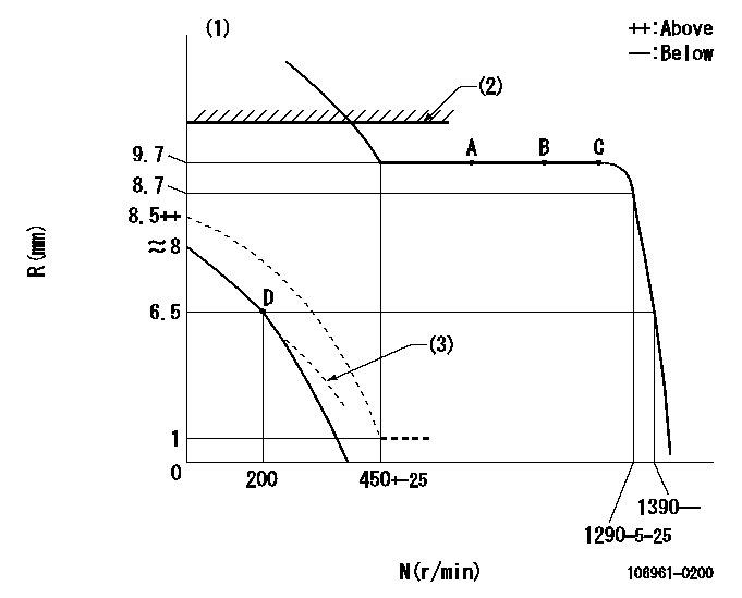
N:Pump speed
R:Rack position (mm)
(1)After completing adjustment of the broken line, set the lever at the unbroken line position.
(2)Rack limit using the stop lever: R1
(3)Beginning of damper spring operation: DL
----------
R1=11.2+0.2mm DL=5.5-0.2mm
----------
----------
R1=11.2+0.2mm DL=5.5-0.2mm
----------
0000000901

F:Full load
I:Idle
(1)Stopper bolt setting
----------
----------
a=12deg+-5deg b=19deg+-3deg
----------
----------
a=12deg+-5deg b=19deg+-3deg
Stop lever angle
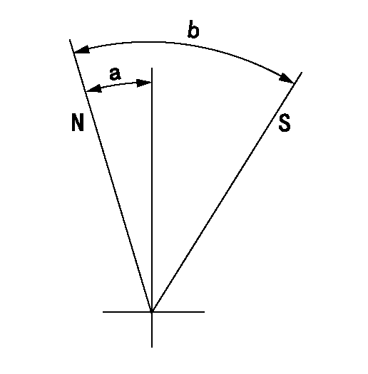
N:Pump normal
S:Stop the pump.
----------
----------
a=12deg+-5deg b=33deg+-3deg
----------
----------
a=12deg+-5deg b=33deg+-3deg
Information:
Guidelines For Reusable Parts; Valves And Valve Springs, SEBF8002 and SEBF8034 have the procedure and specifications necessary for checking used valves and valve springs.(1) 4W2471 Spring for valves (outer) (new): Length under test force ... 53.24 mm (2.096 in)Test force ... 245 24 N (55 5 lb)Use again minimum load at length under test force ... 211 N (48 lb)Length of spring at valve open position ... 39.0 mm (1.54 in)Use again minimum load at valve open position ... 755 N (170 lb)Free length after test ... 59.5 mm (2.34 in)Outside diameter ... 37.31 mm (1.469 in)Spring must not be bent more than ... 2.10 mm (.083 in)(1) 4W2472 Spring for valves (inner) (new): Length under test force ... 50.24 mm (1.978 in)Test force ... 178 18 N (40 4 lb)Use again minimum load at length under test force ... 155 N (35 lb)Length of spring at valve open position ... 36.0 mm (1.42 in)Use again minimum load at valve open position ... 321 N (72 lb)Free length after test ... 65.7 mm (2.60 in)Outside diameter ... 25.13 mm (.989 in)Spring must not be bent more than ... 2.30 mm (.091 in)(2) Height to top of valve guide ... 27.2 .8 mm (1.07 .03 in)(3) Diameter of valve stem (new) ... 9.441 .01 mm (.3717 .0004 in)Use again minimum diameter of valve stems:Exhaust ... 9.408 mm (.3704 in)Inlet ... 9.408 mm (.3704 in)Bore in valve guide with guide installed in the head (new) ... 9.487 0.025 mm (.3735 .0010 in)Use again dimension for valve guide bore ... 9.538 mm (.3755 in)(4) Diameter of valve head: Exhaust valve ... 41.81 0.13 mm (1.646 .005 in)Inlet valve ... 44.98 0.13 mm (1.771 .005 in)(5) Angle of inlet valve face ... 29 1/4 1/4 degreesAngle of exhaust valve face ... 44 1/4 1/4 degrees (6) Depth of bore in head for valve seat insert ... 13.01 0.35 mm (.512 .014 in)(7) Diameter of valve seat insert for inlet valve ... 46.025 0.013 mm (1.8120 .0005 in) Bore in head for valve seat insert for inlet valve ... 45.949 0.025 mm (1.8090 .0010 in)Diameter of valve seat insert for exhaust valve ... 42.850 0.013 mm (1.6870 .0005 in)Bore in head for valve seat insert for exhaust valve ... 42.774 0.025 mm (1.6840 .0010 in)(8) Angle of face of inlet valve seat insert ... 30 1/4 1/2 degreesAngle of face of exhaust valve seat insert ... 44 3/4 1/2 degrees(9) Dimension from end of closed valve to machined face of head. Maximum permissible dimension:Below (recessed from) machined face ... 1.22 mm (.048 in)Above (extended from) machined face ... 0.20