Information injection-pump assembly
ZEXEL
106961-0180
1069610180
Rating:
Service parts 106961-0180 INJECTION-PUMP ASSEMBLY:
1.
_
6.
COUPLING PLATE
7.
COUPLING PLATE
8.
_
9.
_
11.
Nozzle and Holder
16600-97012
12.
Open Pre:MPa(Kqf/cm2)
19.6{200}
15.
NOZZLE SET
Include in #1:
106961-0180
as INJECTION-PUMP ASSEMBLY
Cross reference number
ZEXEL
106961-0180
1069610180
Zexel num
Bosch num
Firm num
Name
106961-0180
INJECTION-PUMP ASSEMBLY
Calibration Data:
Adjustment conditions
Test oil
1404 Test oil ISO4113 or {SAEJ967d}
1404 Test oil ISO4113 or {SAEJ967d}
Test oil temperature
degC
40
40
45
Nozzle
105015-2780
Nozzle holder
105031-4140
Opening pressure
MPa
19.6
Opening pressure
kgf/cm2
200
Injection pipe
Outer diameter - inner diameter - length (mm) mm 6-2-1050
Outer diameter - inner diameter - length (mm) mm 6-2-1050
Overflow valve
132424-0620
Overflow valve opening pressure
kPa
157
123
191
Overflow valve opening pressure
kgf/cm2
1.6
1.25
1.95
Tester oil delivery pressure
kPa
157
157
157
Tester oil delivery pressure
kgf/cm2
1.6
1.6
1.6
Direction of rotation (viewed from drive side)
Right R
Right R
Injection timing adjustment
Direction of rotation (viewed from drive side)
Right R
Right R
Injection order
10-9-4-3
-6-5-8-7
-2-1
Pre-stroke
mm
3.65
3.6
3.7
Beginning of injection position
Governor side NO.1
Governor side NO.1
Difference between angles 1
Cal 10-9 deg. 45 44.5 45.5
Cal 10-9 deg. 45 44.5 45.5
Difference between angles 2
Cal 10-4 deg. 72 71.5 72.5
Cal 10-4 deg. 72 71.5 72.5
Difference between angles 3
Cal 10-3 deg. 117 116.5 117.5
Cal 10-3 deg. 117 116.5 117.5
Difference between angles 4
Cal 10-6 deg. 144 143.5 144.5
Cal 10-6 deg. 144 143.5 144.5
Difference between angles 5
Cal 10-5 deg. 189 188.5 189.5
Cal 10-5 deg. 189 188.5 189.5
Difference between angles 6
Cal 10-8 deg. 216 215.5 216.5
Cal 10-8 deg. 216 215.5 216.5
Difference between angles 7
Cal 10-7 deg. 261 260.5 261.5
Cal 10-7 deg. 261 260.5 261.5
Difference between angles 8
Cal 10-2 deg. 288 287.5 288.5
Cal 10-2 deg. 288 287.5 288.5
Difference between angles 9
Cal 10-1 deg. 333 332.5 333.5
Cal 10-1 deg. 333 332.5 333.5
Injection quantity adjustment
Adjusting point
A
Rack position
10.9
Pump speed
r/min
700
700
700
Average injection quantity
mm3/st.
118
118
120
Max. variation between cylinders
%
0
-4
4
Basic
*
Fixing the lever
*
Injection quantity adjustment_02
Adjusting point
B
Rack position
10.9
Pump speed
r/min
1000
1000
1000
Average injection quantity
mm3/st.
113.5
110.5
116.5
Max. variation between cylinders
%
0
-4
4
Fixing the lever
*
Injection quantity adjustment_03
Adjusting point
C
Rack position
10.9
Pump speed
r/min
1200
1200
1200
Average injection quantity
mm3/st.
107
103
111
Max. variation between cylinders
%
0
-4
4
Fixing the lever
*
Injection quantity adjustment_04
Adjusting point
D
Rack position
4.5+-0.5
Pump speed
r/min
250
250
250
Average injection quantity
mm3/st.
20
18
22
Max. variation between cylinders
%
0
-10
10
Fixing the rack
*
Timer adjustment
Pump speed
r/min
300+100
Advance angle
deg.
0
0
0
Remarks
Start
Start
Timer adjustment_02
Pump speed
r/min
700
Advance angle
deg.
1.7
1.2
2.2
Timer adjustment_03
Pump speed
r/min
1000
Advance angle
deg.
3.5
3
4
Timer adjustment_04
Pump speed
r/min
1250+50
Advance angle
deg.
5.5
5
6
Remarks
Finish
Finish
Test data Ex:
Governor adjustment
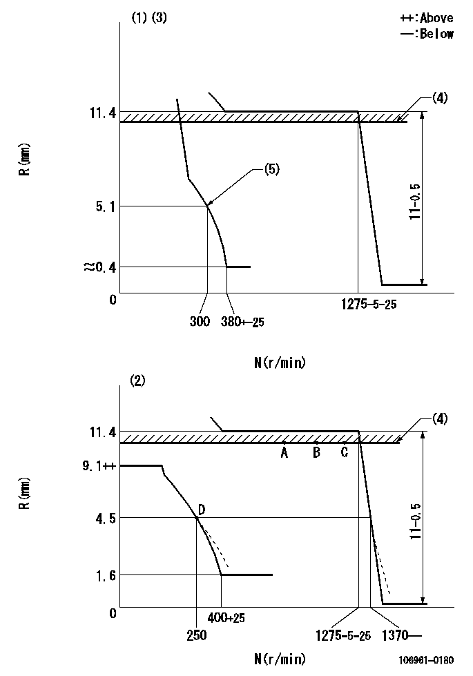
N:Pump speed
R:Rack position (mm)
(1)Adjust with speed control lever at full position (minimum-maximum speed specification)
(2)Adjust with the load control lever in the full position (variable speed specification).
(3)Beginning of damper spring operation: DL
(4)RACK LIMIT: RAL (set using stop lever)
(5)Set using the speed control lever (idle spring does not operate).
----------
DL=4.4-0.2mm RAL=10.9mm
----------
----------
DL=4.4-0.2mm RAL=10.9mm
----------
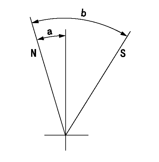
Speed control lever angle
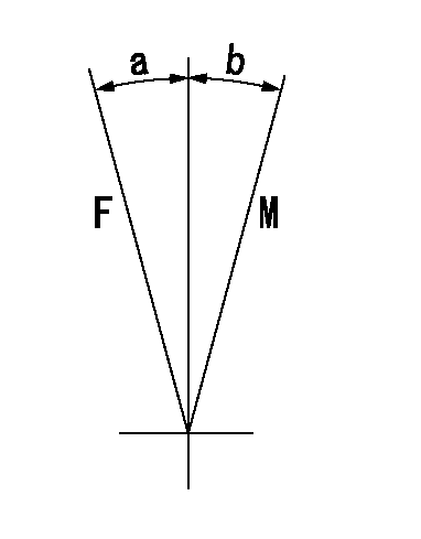
F:Full speed
M:Minimum-maximum speed
----------
----------
a=12deg+-5deg b=10deg+-5deg
----------
----------
a=12deg+-5deg b=10deg+-5deg
0000000901
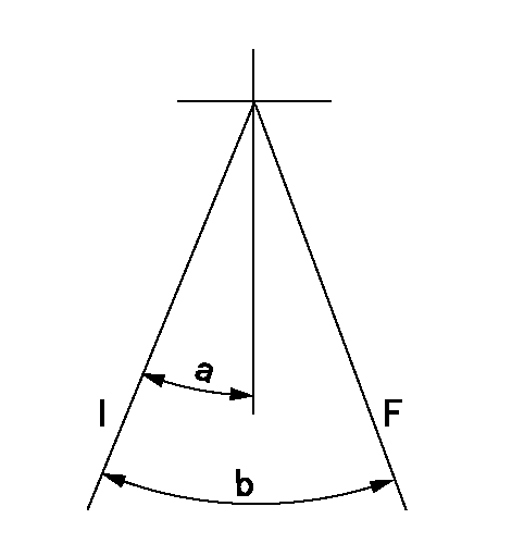
F:Full load
I:Idle
----------
----------
a=27deg+-5deg b=36deg+-3deg
----------
----------
a=27deg+-5deg b=36deg+-3deg
Stop lever angle
N:Pump normal
S:Stop the pump.
----------
----------
a=1.5deg+-5deg b=28deg+-3deg
----------
----------
a=1.5deg+-5deg b=28deg+-3deg
Information:
The troubleshooting chart provides a definite sequence to be followed for a logical procedure to determine the frequency and amplitude of vibration so that the source of the vibration can be located and corrected.1. The customer must be asked questions to determine whether his complaint is valid, or whether his diagnosis of the actual problem is correct.Some of the questions that must be asked are as follows:a. What components are vibrating?b. In what speed range does this vibration become excessive?c. Does clutch operation affect the vibration?d. What is the history of the problem?2. Run the engine through the idle speed range and note all vibrating components. Look for any loose or broken mounts, brackets, and fasteners. Repair and tighten any fixtures.3. Check idle speed range with clutch disengaged. If vibrations subside, there is a balance problem with the clutch disc. The clutch disc must be repaired or replaced.4. Further analysis requires the use of a vibration instrument. Any instrument which can accurately measure the displacement of the vibration (usually in mils-inch/1000) and the frequency (cycles per second) will be sufficient. A vibration instrument such as the IRD Mechanalysis Model 320 or an equivalent instrument can be used to analyze vibration.5. Measure vibration of cab components which have the objectionable vibration.Run engine slowly through the speed range and measure vibration with the instrument filter OUT. When peak amplitudes are found, run the engine at the speeds they occur and with the instrument filter IN, find the frequency of the vibration.If the frequency of vibration is 1/2 times of engine rpm (1/2 order), the vibration is caused by a cylinder misfiring. This must be corrected before further vibration analysis is made.If the frequency of vibration is 3 times engine rpm, no corrective action can be taken on the engine because this is the firing frequency of the 3306 engine. The problem is in the cab or chassis resonance.If frequency is some order other than 1/2 or 3rd, then further measurements must be made on the engine.6. Measurements taken on the engine must be made perpendicular to the crankshaft at the front and, rear of the engine in vertical and horizontal directions.7. Record all vibrations over 4.0 mils and the engine rpm at which it occurs (100 rpm intervals are sufficient) with instrument filter OUT. Note any sudden increase and decrease in amplitudes. These occur in resonant speed ranges.If no amplitudes exceed 4.0 mils, the engine is within Caterpillar Specifications.If amplitudes exceed 4.0 mils, the vibrations must be measured with the instrument filter IN to obtain the frequency of the vibrations.8. Run the engine at high idle. With the instrument filter IN, check the frequency range and record any amplitudes over 4.0 mils and the corresponding frequency. Analysis of vibrations for the possible causes is done by identifying the frequency of the vibration and where on the engine it is the greatest magnitude. Make reference to Special Instruction, Troubleshooting Engine Vibration In Vehicular Equipment, SEHS7914 for additional information for troubleshooting vibration complaints.
Have questions with 106961-0180?
Group cross 106961-0180 ZEXEL
Nissan-Diesel
Nissan-Diesel
Nissan-Diesel
Nissan-Diesel
106961-0180
INJECTION-PUMP ASSEMBLY