Information injection-pump assembly
ZEXEL
106961-0170
1069610170
Rating:
Cross reference number
ZEXEL
106961-0170
1069610170
Zexel num
Bosch num
Firm num
Name
106961-0170
INJECTION-PUMP ASSEMBLY
Calibration Data:
Adjustment conditions
Test oil
1404 Test oil ISO4113 or {SAEJ967d}
1404 Test oil ISO4113 or {SAEJ967d}
Test oil temperature
degC
40
40
45
Nozzle
105015-2780
Bosch type code
DLLA166S374NP6
Nozzle holder
105031-4140
Opening pressure
MPa
19.6
Opening pressure
kgf/cm2
200
Injection pipe
Outer diameter - inner diameter - length (mm) mm 6-2-1050
Outer diameter - inner diameter - length (mm) mm 6-2-1050
Overflow valve
132424-0620
Overflow valve opening pressure
kPa
157
123
191
Overflow valve opening pressure
kgf/cm2
1.6
1.25
1.95
Tester oil delivery pressure
kPa
157
157
157
Tester oil delivery pressure
kgf/cm2
1.6
1.6
1.6
Direction of rotation (viewed from drive side)
Right R
Right R
Injection timing adjustment
Direction of rotation (viewed from drive side)
Right R
Right R
Injection order
10-9-4-3
-6-5-8-7
-2-1
Pre-stroke
mm
3.65
3.6
3.7
Beginning of injection position
Governor side NO.1
Governor side NO.1
Difference between angles 1
Cal 10-9 deg. 45 44.5 45.5
Cal 10-9 deg. 45 44.5 45.5
Difference between angles 2
Cal 10-4 deg. 72 71.5 72.5
Cal 10-4 deg. 72 71.5 72.5
Difference between angles 3
Cal 10-3 deg. 117 116.5 117.5
Cal 10-3 deg. 117 116.5 117.5
Difference between angles 4
Cal 10-6 deg. 144 143.5 144.5
Cal 10-6 deg. 144 143.5 144.5
Difference between angles 5
Cal 10-5 deg. 189 188.5 189.5
Cal 10-5 deg. 189 188.5 189.5
Difference between angles 6
Cal 10-8 deg. 216 215.5 216.5
Cal 10-8 deg. 216 215.5 216.5
Difference between angles 7
Cal 10-7 deg. 261 260.5 261.5
Cal 10-7 deg. 261 260.5 261.5
Difference between angles 8
Cal 10-2 deg. 288 287.5 288.5
Cal 10-2 deg. 288 287.5 288.5
Difference between angles 9
Cal 10-1 deg. 333 332.5 333.5
Cal 10-1 deg. 333 332.5 333.5
Injection quantity adjustment
Adjusting point
A
Rack position
10.6
Pump speed
r/min
750
750
750
Average injection quantity
mm3/st.
112
110
114
Max. variation between cylinders
%
0
-4
4
Basic
*
Fixing the lever
*
Injection quantity adjustment_02
Adjusting point
B
Rack position
10.6
Pump speed
r/min
880
880
880
Average injection quantity
mm3/st.
110
108
112
Max. variation between cylinders
%
0
-4
4
Fixing the lever
*
Injection quantity adjustment_03
Adjusting point
C
Rack position
6.1+-0.5
Pump speed
r/min
300
300
300
Average injection quantity
mm3/st.
20
18
22
Max. variation between cylinders
%
0
-10
10
Fixing the rack
*
Timer adjustment
Pump speed
r/min
300+100
Advance angle
deg.
0
0
0
Remarks
Start
Start
Timer adjustment_02
Pump speed
r/min
700
Advance angle
deg.
3
2.5
3.5
Timer adjustment_03
Pump speed
r/min
1000
Advance angle
deg.
5.6
5.1
6.1
Timer adjustment_04
Pump speed
r/min
1250+50
Advance angle
deg.
8
7.5
8.5
Remarks
Finish
Finish
Test data Ex:
Governor adjustment
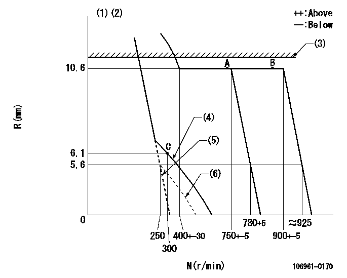
N:Pump speed
R:Rack position (mm)
(1)Target notch: K
(2)Solenoid operation confirmation: Set the speed control lever in the full speed position. At pump speed N1 when the solenoid is operated, confirm that the idle rack position is R1 or less. Confirm using the manual lever in the same way.
(3)RACK LIMIT: RAL
(4)After setting the idle sub-spring, adjust using the idle spring.
(5)At pump speed N2, set the control lever stopper bolt (minimum speed setting) so that the rack position is R2.
(6)Idle sub spring setting: L1.
----------
K=7 N1=100r/min R1=-1mm RAL=10.9+-0.1mm N2=250r/min R2=7mm L1=6.1-0.5mm
----------
----------
K=7 N1=100r/min R1=-1mm RAL=10.9+-0.1mm N2=250r/min R2=7mm L1=6.1-0.5mm
----------
Speed control lever angle
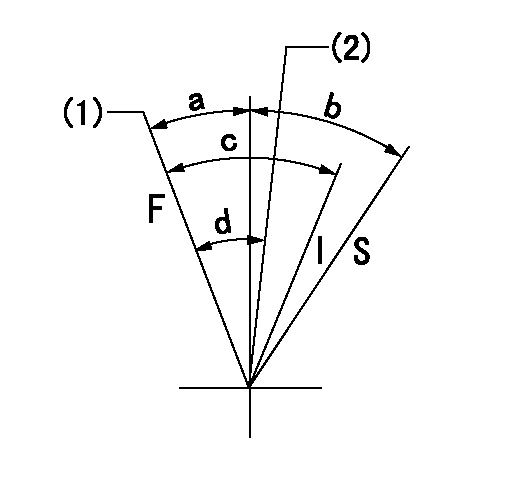
F:Full speed
I:Idle
S:Stop
(1)Pump speed = aa
(2)Pump speed = bb
----------
aa=900r/min bb=750r/min
----------
a=5deg+-5deg b=(32deg+-3deg) c=30deg+-5deg d=7deg+-5deg
----------
aa=900r/min bb=750r/min
----------
a=5deg+-5deg b=(32deg+-3deg) c=30deg+-5deg d=7deg+-5deg
Stop lever angle

N:Pump normal
S:Stop the pump.
----------
----------
a=(29deg) b=(47deg)
----------
----------
a=(29deg) b=(47deg)
Information:
Overheating
Possible Causes/Corrections Low Coolant LevelIf the coolant level is too low, not enough coolant will go through the engine and radiator. This lack of coolant will not take enough heat from the engine and there will not be enough flow of coolant through the radiator to release the heat into the cooling air. Low coolant level is caused by leaks or wrong filling of the radiator. With the engine cool, be sure that coolant can be seen at the low end of the fill neck on the radiator top tank. Defective Temperature GaugeA temperature gauge which does not work correctly will not show the correct temperature. If the temperature gauge shows that the coolant temperature is too hot but other conditions are normal, either install a gauge you know is good or check the cooling system with the 4C6500 Digital Thermometer Group. Dirty RadiatorCheck the radiator for debris between the fins of the radiator core which prevents free air flow through the radiator core. Check the radiator for debris, dirt, or deposits on the inside of the radiator core which prevents free flow of coolant through the radiator. Loose Belt(s)Loose fan or water pump belts will cause a reduction in air or water flow. Tighten the belts according to Belt Tension Chart that is shown in Specification Section of this Service Manual. Defective Hose(s)Defective hoses with leaks can normally be seen. Hoses that have no visual leaks can "collapse" (pull together) during operation and cause a restriction in the flow of coolant. Hoses become soft and/or get cracks after a period of time. Hoses must be changed after 50,000 miles or a year of use. The inside can become loose, and the loose particles of the hose can cause a restriction in the flow of coolant. Shunt Line RestrictionA restriction of the shunt line from the radiator top tank to the engine front cover, or a shunt line not installed correctly, will cause a reduction in water pump efficientcy. The result will be low coolant flow and overheating. Shutters Not Opening CorrectlyCheck the opening temperature of the shutters. The shutters must be completely closed at a temperature below the fully open temperature of the water temperature regulators. Also, verify that fan control switches or viscous fans are operating correctly. Defective Water Temperature RegulatorsA regulator that does not open, or only opens part of the way, can cause above normal heating. To test the thermostats, see the Testing and Adjusting Section of this Service Manual. Defective Water PumpA water pump with a loose impeller does not pump enough coolant for correct engine cooling. A loose impeller can be found by removing the water pump, and by pushing the shaft back and pulling it forward. If the impeller has no damage, check the impeller clearance. The clearance between the impeller and the housing is 0.56 to 1.50 mm (.022 to .059 in). Air In Cooling SystemAir can get into the cooling system in different ways. The most common causes are
Possible Causes/Corrections Low Coolant LevelIf the coolant level is too low, not enough coolant will go through the engine and radiator. This lack of coolant will not take enough heat from the engine and there will not be enough flow of coolant through the radiator to release the heat into the cooling air. Low coolant level is caused by leaks or wrong filling of the radiator. With the engine cool, be sure that coolant can be seen at the low end of the fill neck on the radiator top tank. Defective Temperature GaugeA temperature gauge which does not work correctly will not show the correct temperature. If the temperature gauge shows that the coolant temperature is too hot but other conditions are normal, either install a gauge you know is good or check the cooling system with the 4C6500 Digital Thermometer Group. Dirty RadiatorCheck the radiator for debris between the fins of the radiator core which prevents free air flow through the radiator core. Check the radiator for debris, dirt, or deposits on the inside of the radiator core which prevents free flow of coolant through the radiator. Loose Belt(s)Loose fan or water pump belts will cause a reduction in air or water flow. Tighten the belts according to Belt Tension Chart that is shown in Specification Section of this Service Manual. Defective Hose(s)Defective hoses with leaks can normally be seen. Hoses that have no visual leaks can "collapse" (pull together) during operation and cause a restriction in the flow of coolant. Hoses become soft and/or get cracks after a period of time. Hoses must be changed after 50,000 miles or a year of use. The inside can become loose, and the loose particles of the hose can cause a restriction in the flow of coolant. Shunt Line RestrictionA restriction of the shunt line from the radiator top tank to the engine front cover, or a shunt line not installed correctly, will cause a reduction in water pump efficientcy. The result will be low coolant flow and overheating. Shutters Not Opening CorrectlyCheck the opening temperature of the shutters. The shutters must be completely closed at a temperature below the fully open temperature of the water temperature regulators. Also, verify that fan control switches or viscous fans are operating correctly. Defective Water Temperature RegulatorsA regulator that does not open, or only opens part of the way, can cause above normal heating. To test the thermostats, see the Testing and Adjusting Section of this Service Manual. Defective Water PumpA water pump with a loose impeller does not pump enough coolant for correct engine cooling. A loose impeller can be found by removing the water pump, and by pushing the shaft back and pulling it forward. If the impeller has no damage, check the impeller clearance. The clearance between the impeller and the housing is 0.56 to 1.50 mm (.022 to .059 in). Air In Cooling SystemAir can get into the cooling system in different ways. The most common causes are
Have questions with 106961-0170?
Group cross 106961-0170 ZEXEL
Nissan-Diesel
Nissan-Diesel
Nissan-Diesel
106961-0170
INJECTION-PUMP ASSEMBLY