Information injection-pump assembly
ZEXEL
106961-0111
1069610111

Rating:
Cross reference number
ZEXEL
106961-0111
1069610111
Zexel num
Bosch num
Firm num
Name
106961-0111
INJECTION-PUMP ASSEMBLY
Calibration Data:
Adjustment conditions
Test oil
1404 Test oil ISO4113 or {SAEJ967d}
1404 Test oil ISO4113 or {SAEJ967d}
Test oil temperature
degC
40
40
45
Nozzle
105015-2780
Bosch type code
DLLA166S374NP6
Nozzle holder
105031-4190
Opening pressure
MPa
19.6
Opening pressure
kgf/cm2
200
Injection pipe
Outer diameter - inner diameter - length (mm) mm 6-2-1050
Outer diameter - inner diameter - length (mm) mm 6-2-1050
Overflow valve opening pressure
kPa
157
123
191
Overflow valve opening pressure
kgf/cm2
1.6
1.25
1.95
Tester oil delivery pressure
kPa
157
157
157
Tester oil delivery pressure
kgf/cm2
1.6
1.6
1.6
Direction of rotation (viewed from drive side)
Right R
Right R
Injection timing adjustment
Direction of rotation (viewed from drive side)
Right R
Right R
Injection order
10-9-4-3
-6-5-8-7
-2-1
Pre-stroke
mm
3.65
3.6
3.7
Beginning of injection position
Governor side NO.1
Governor side NO.1
Difference between angles 1
Cal 10-9 deg. 45 44.5 45.5
Cal 10-9 deg. 45 44.5 45.5
Difference between angles 2
Cal 10-4 deg. 72 71.5 72.5
Cal 10-4 deg. 72 71.5 72.5
Difference between angles 3
Cal 10-3 deg. 117 116.5 117.5
Cal 10-3 deg. 117 116.5 117.5
Difference between angles 4
Cal 10-6 deg. 144 143.5 144.5
Cal 10-6 deg. 144 143.5 144.5
Difference between angles 5
Cal 10-5 deg. 189 188.5 189.5
Cal 10-5 deg. 189 188.5 189.5
Difference between angles 6
Cal 10-8 deg. 216 215.5 216.5
Cal 10-8 deg. 216 215.5 216.5
Difference between angles 7
Cal 10-7 deg. 261 260.5 261.5
Cal 10-7 deg. 261 260.5 261.5
Difference between angles 8
Cal 10-2 deg. 288 287.5 288.5
Cal 10-2 deg. 288 287.5 288.5
Difference between angles 9
Cal 10-1 deg. 333 332.5 333.5
Cal 10-1 deg. 333 332.5 333.5
Injection quantity adjustment
Adjusting point
A
Rack position
10.2
Pump speed
r/min
700
700
700
Average injection quantity
mm3/st.
103
102
104
Max. variation between cylinders
%
0
-4
4
Basic
*
Fixing the lever
*
Injection quantity adjustment_02
Adjusting point
B
Rack position
10.2
Pump speed
r/min
950
950
950
Average injection quantity
mm3/st.
97
94
100
Max. variation between cylinders
%
0
-4
4
Fixing the lever
*
Injection quantity adjustment_03
Adjusting point
C
Rack position
6+-0.5
Pump speed
r/min
225
225
225
Average injection quantity
mm3/st.
20
18
22
Max. variation between cylinders
%
0
-10
10
Fixing the rack
*
Timer adjustment
Pump speed
r/min
300+100
Advance angle
deg.
0
0
0
Remarks
Start
Start
Timer adjustment_02
Pump speed
r/min
700
Advance angle
deg.
3
2.5
3.5
Timer adjustment_03
Pump speed
r/min
1000
Advance angle
deg.
5.6
5.1
6.1
Timer adjustment_04
Pump speed
r/min
1250+50
Advance angle
deg.
8
7.5
8.5
Remarks
Finish
Finish
Test data Ex:
Governor adjustment
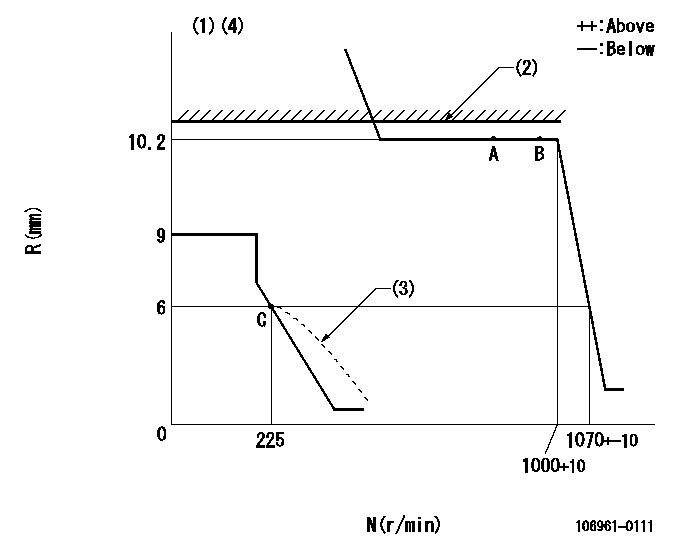
N:Pump speed
R:Rack position (mm)
(1)Target notch: K
(2)RACK LIMIT: RAL
(3)Beginning of damper spring operation: DL
(4)Solenoid operation confirmation: Set the speed control lever in the full speed position. At pump speed N1 when the solenoid is operated, confirm that the idle rack position is R1 or less.
----------
K=10 RAL=10.9+-0.1mm DL=6-0.5mm N1=100r/min R1=1mm
----------
----------
K=10 RAL=10.9+-0.1mm DL=6-0.5mm N1=100r/min R1=1mm
----------
Speed control lever angle

F:Full speed
I:Idle
S:Stop
----------
----------
a=8deg+-5deg b=32deg+-3deg c=23deg+-5deg
----------
----------
a=8deg+-5deg b=32deg+-3deg c=23deg+-5deg
Stop lever angle

N:Pump normal
S:Stop the pump.
----------
----------
a=(29deg) b=(47deg)
----------
----------
a=(29deg) b=(47deg)
Information:
Recommended Procedure With Chassis Dynamometer
Possible Causes/Corrections Minor Operating FaultsTo help identify a problem before a more involved troubleshooting procedure is started, follow the procedure given in the "Primary Engine Checks" section. Fuel Ratio Control Out Of Adjustment Or DefectiveFollow the procedure in the Testing and Adjusting Section of this Service Manual. Check Engine PerformanceDo a Power Analysis Report (PAR), Level II, to check engine performance. Refer to LEBV2810 and SEHS7886 for the tooling and procedures to use. Be sure to make a record of the temperatures for inlet air, fuel (at filter base), lubricating oil and coolant. Make the necessary adjustments or repairs to the engine if needed.At this point, the governor fuel settings should be verified. See the Testing and Adjusting Section of this Service Manual for the necessary procedures. Also, refer back to the information learned earlier (see "Owner/Operator Input" section) about the truck specifications and application and judge whether or not the engine is performing as expected or customer expectation is realistic.Recommended Procedure Without Chassis Dynamometer
Possible Causes/Corrections Minor Operating FaultsTo help identify a problem before a more involved troubleshooting procedure is started, follow the procedure given in the "Primary Engine Checks" section. Fuel Ratio Control Out Of Adjustment Or DefectiveFollow the procedure in the Testing and Adjusting Section of this Service Manual. Fuel Injection Timing Not CorrectFollow the procedures in the Testing and Adjusting Section of this Service Manual. Check Engine PerformanceInstall the tooling and follow the procedure given in the Road Test section.At this point, the governor fuel settings should be verified. See the Testing and Adjusting Section of this Service Manual for the necessary procedures. Also, refer back to the information learned earlier (see "Owner/Operator Input" section) about the truck specifications and application and judge whether or not the engine is performing as expected or customer expectation is realistic.
Have questions with 106961-0111?
Group cross 106961-0111 ZEXEL
Nissan-Diesel
106961-0111
INJECTION-PUMP ASSEMBLY