Information injection-pump assembly
ZEXEL
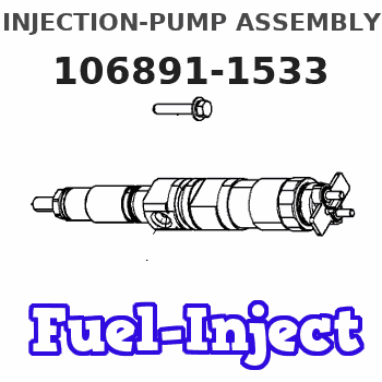
106891-1533
1068911533
ISUZU
1156031882
1156031882
Rating:
Cross reference number
ZEXEL
106891-1533
1068911533
ISUZU
1156031882
1156031882
Zexel num
Bosch num
Firm num
Name
Calibration Data:
Adjustment conditions
Test oil
1404 Test oil ISO4113 or {SAEJ967d}
1404 Test oil ISO4113 or {SAEJ967d}
Test oil temperature
degC
40
40
45
Nozzle and nozzle holder
105780-8250
Bosch type code
1 688 901 101
Nozzle
105780-0120
Bosch type code
1 688 901 990
Nozzle holder
105780-2190
Opening pressure
MPa
20.7
Opening pressure
kgf/cm2
211
Injection pipe
Outer diameter - inner diameter - length (mm) mm 8-3-600
Outer diameter - inner diameter - length (mm) mm 8-3-600
Overflow valve
134424-4320
Overflow valve opening pressure
kPa
255
221
289
Overflow valve opening pressure
kgf/cm2
2.6
2.25
2.95
Tester oil delivery pressure
kPa
255
255
255
Tester oil delivery pressure
kgf/cm2
2.6
2.6
2.6
RED3 control unit part number
407910-3
960
RED3 rack sensor specifications
mm
19
Direction of rotation (viewed from drive side)
Right R
Right R
Injection timing adjustment
Direction of rotation (viewed from drive side)
Right R
Right R
Injection order
1-8-7-3-
6-5-4-2
Pre-stroke
mm
5.5
5.47
5.53
Rack position
Point A R=A
Point A R=A
Beginning of injection position
Governor side NO.1
Governor side NO.1
Difference between angles 1
Cal 1-8 deg. 45 44.75 45.25
Cal 1-8 deg. 45 44.75 45.25
Difference between angles 2
Cal 1-7 deg. 90 89.75 90.25
Cal 1-7 deg. 90 89.75 90.25
Difference between angles 3
Cal 1-3 deg. 135 134.75 135.25
Cal 1-3 deg. 135 134.75 135.25
Difference between angles 4
Cal 1-6 deg. 180 179.75 180.25
Cal 1-6 deg. 180 179.75 180.25
Difference between angles 5
Cal 1-5 deg. 225 224.75 225.25
Cal 1-5 deg. 225 224.75 225.25
Difference between angles 6
Cal 1-4 deg. 270 269.75 270.25
Cal 1-4 deg. 270 269.75 270.25
Difference between angles 7
Cyl.1-2 deg. 315 314.75 315.25
Cyl.1-2 deg. 315 314.75 315.25
Injection quantity adjustment
Rack position
(12.1)
Vist
V
2.04
2.04
2.04
Pump speed
r/min
700
700
700
Average injection quantity
mm3/st.
148
147
149
Max. variation between cylinders
%
0
-3
3
Basic
*
Remarks
Point A
Point A
Injection quantity adjustment_02
Rack position
(6.2)
Vist
V
2.9
2.8
3
Pump speed
r/min
425
425
425
Average injection quantity
mm3/st.
13.5
11.5
15.5
Max. variation between cylinders
%
0
-13
13
Test data Ex:
Governor adjustment

(1)Adjusting range
(2)Step response time
(N): Speed of the pump
(L): Load
(theta) Advance angle
(Srd1) Step response time 1
(Srd2) Step response time 2
1. Adjusting conditions for the variable timer
(1)Adjust the clearance between the pickup and the protrusion to L.
----------
L=1-0.2mm N2=800r/min C2=(8)deg t1=1.5--sec. t2=1.5--sec.
----------
N1=950++r/min P1=0kPa(0kgf/cm2) P2=392kPa(4kgf/cm2) C1=8+-0.3deg R01=0/4load R02=4/4load
----------
L=1-0.2mm N2=800r/min C2=(8)deg t1=1.5--sec. t2=1.5--sec.
----------
N1=950++r/min P1=0kPa(0kgf/cm2) P2=392kPa(4kgf/cm2) C1=8+-0.3deg R01=0/4load R02=4/4load
Speed control lever angle

N:Pump normal
S:Stop the pump.
(1)Rack position = aa
(2)Rack position bb
----------
aa=20mm bb=1mm
----------
a=37deg+-5deg b=37deg+-5deg
----------
aa=20mm bb=1mm
----------
a=37deg+-5deg b=37deg+-5deg
0000000901

(1)Pump vertical direction
(2)Position of "Z" mark at the No 1 cylinder's beginning of injection (governor side)
(3)B.T.D.C.: aa
(4)-
----------
aa=4deg
----------
a=(180deg)
----------
aa=4deg
----------
a=(180deg)
Stop lever angle

(Rs) rack sensor specifications
(C/U) control unit part number
(V) Rack sensor output voltage
(R) Rack position (mm)
1. Confirming governor output characteristics (rack 19 mm, span 6 mm)
(1)When the output voltages of the rack sensor are V1 and V2, check that the rack positions R1 and R2 in the table above are satisfied.
----------
----------
----------
----------
Information:
Start By:a. remove flywheelb. remove crankshaft rear seal 1. Install Tool (A) in the bore for the crankshaft rear seal as shown.2. Install Tool (B) between Tool (A) and the crankshaft wear sleeve. Turn Tool (B) until the edge of the tool makes a crease in the crankshaft wear sleeve. Repeat this in two more locations around the crankshaft wear sleeve until it is loose.3. Remove Tool (A) and the crankshaft wear sleeve from the end of the crankshaft.Install Salvaged Crankshaft Wear Sleeve
1. Be sure the flange of the crankshaft is thoroughly clean prior to installing the crankshaft wear sleeve.
The crankshaft wear sleeve has a taper on the outside diameter. It must be installed correctly on the crankshaft.
2. Put crankshaft wear sleeve (1) in position on the 1U7597 Sleeve Ring [part of Tool (A)]. Be sure the taper on the outside diameter of the wear sleeve is facing away from the sleeve ring as shown.3. Fasten the 1U7595 Locator Assembly [part of Tool (A)] to the rear of the crankshaft. 4. Position crankshaft wear sleeve (1), with the sleeve ring, over the locator assembly as shown.5. Install the 1U7594 Installer [part of Tool (A)] over the locator assembly. Tighten the nut assembly of Tool (A) to push the crankshaft wear sleeve into position on the crankshaft.6. Remove the installer and the sleeve ring from the locator assembly. Turn the sleeve ring around, and install it and the installer back on the locator assembly. Tighten the nut assembly of Tool (A) to complete the installation of the crankshaft wear sleeve.End By:a. install crankshaft rear sealb install flywheel