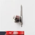
Information injection-pump assembly
BOSCH
F 019 Z10 902
f019z10902
ZEXEL
106891-1303
1068911303
ISUZU
1156025613
1156025613
Rating:
Service parts 106891-1303 INJECTION-PUMP ASSEMBLY:
1.
_
6.
COUPLING PLATE
7.
COUPLING PLATE
8.
_
9.
_
11.
Nozzle and Holder
12.
Open Pre:MPa(Kqf/cm2)
15.7(160)/22.1(225)
15.
NOZZLE SET
Include in #1:
106891-1303
as INJECTION-PUMP ASSEMBLY
Cross reference number
BOSCH
F 019 Z10 902
f019z10902
ZEXEL
106891-1303
1068911303
ISUZU
1156025613
1156025613
Zexel num
Bosch num
Firm num
Name
Calibration Data:
Adjustment conditions
Test oil
1404 Test oil ISO4113 or {SAEJ967d}
1404 Test oil ISO4113 or {SAEJ967d}
Test oil temperature
degC
40
40
45
Nozzle and nozzle holder
105780-8140
Bosch type code
EF8511/9A
Nozzle
105780-0000
Bosch type code
DN12SD12T
Nozzle holder
105780-2080
Bosch type code
EF8511/9
Opening pressure
MPa
17.2
Opening pressure
kgf/cm2
175
Injection pipe
Outer diameter - inner diameter - length (mm) mm 8-3-600
Outer diameter - inner diameter - length (mm) mm 8-3-600
Overflow valve (drive side)
134424-4020
Overflow valve opening pressure (drive side)
kPa
255
221
289
Overflow valve opening pressure (drive side)
kgf/cm2
2.6
2.25
2.95
Overflow valve (governor side)
134424-2720
Overflow valve opening pressure (governor side)
kPa
255
221
289
Overflow valve opening pressure (governor side)
kgf/cm2
2.6
2.25
2.95
Tester oil delivery pressure
kPa
157
157
157
Tester oil delivery pressure
kgf/cm2
1.6
1.6
1.6
Direction of rotation (viewed from drive side)
Right R
Right R
Injection timing adjustment
Direction of rotation (viewed from drive side)
Right R
Right R
Injection order
1-8-7-3-
6-5-4-2
Pre-stroke
mm
4.2
4.17
4.23
Rack position
Point A R=A
Point A R=A
Beginning of injection position
Governor side NO.1
Governor side NO.1
Difference between angles 1
Cal 1-8 deg. 45 44.75 45.25
Cal 1-8 deg. 45 44.75 45.25
Difference between angles 2
Cal 1-7 deg. 90 89.75 90.25
Cal 1-7 deg. 90 89.75 90.25
Difference between angles 3
Cal 1-3 deg. 135 134.75 135.25
Cal 1-3 deg. 135 134.75 135.25
Difference between angles 4
Cal 1-6 deg. 180 179.75 180.25
Cal 1-6 deg. 180 179.75 180.25
Difference between angles 5
Cal 1-5 deg. 225 224.75 225.25
Cal 1-5 deg. 225 224.75 225.25
Difference between angles 6
Cal 1-4 deg. 270 269.75 270.25
Cal 1-4 deg. 270 269.75 270.25
Difference between angles 7
Cyl.1-2 deg. 315 314.75 315.25
Cyl.1-2 deg. 315 314.75 315.25
Injection quantity adjustment
Adjusting point
A
Rack position
7.3
Pump speed
r/min
800
800
800
Average injection quantity
mm3/st.
87.8
86.3
89.3
Max. variation between cylinders
%
0
-2
2
Basic
*
Fixing the lever
*
Injection quantity adjustment_02
Adjusting point
B
Rack position
7.5
Pump speed
r/min
500
500
500
Average injection quantity
mm3/st.
77.9
75.9
79.9
Fixing the lever
*
Injection quantity adjustment_03
Adjusting point
C
Rack position
7.3
Pump speed
r/min
1200
1200
1200
Average injection quantity
mm3/st.
106.5
102.5
110.5
Fixing the lever
*
Injection quantity adjustment_04
Adjusting point
D
Rack position
4.8+-0.5
Pump speed
r/min
225
225
225
Average injection quantity
mm3/st.
8.7
7.4
10
Max. variation between cylinders
%
0
-13
13
Fixing the rack
*
Timer adjustment
Pump speed
r/min
950--
Advance angle
deg.
0
0
0
Load
3/4
Remarks
Start
Start
Timer adjustment_02
Pump speed
r/min
900
Advance angle
deg.
0.3
Load
3/4
Timer adjustment_03
Pump speed
r/min
-
Advance angle
deg.
0
0
0
Load
4/4
Remarks
Measure speed (beginning of operation).
Measure speed (beginning of operation).
Timer adjustment_04
Pump speed
r/min
1150
Advance angle
deg.
5
4.5
5.5
Load
4/4
Remarks
Finish
Finish
Test data Ex:
Governor adjustment
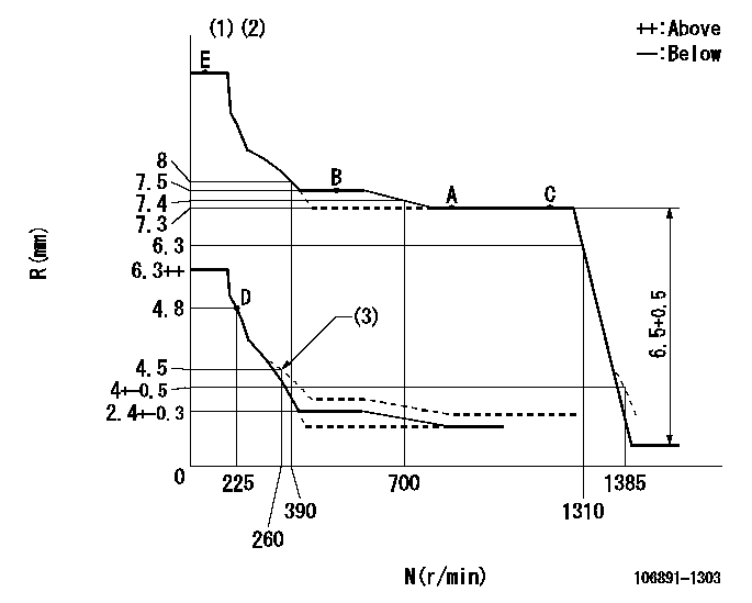
N:Pump speed
R:Rack position (mm)
(1)Tolerance for racks not indicated: +-0.05mm.
(2)Supplied with torque spring not set.
(3)Damper spring setting
----------
----------
----------
----------
Speed control lever angle

F:Full speed
----------
----------
a=8deg+-5deg
----------
----------
a=8deg+-5deg
0000000901
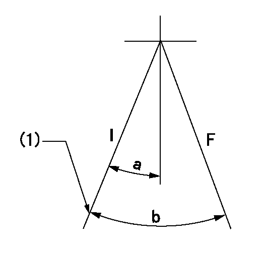
F:Full load
I:Idle
(1)Stopper bolt setting
----------
----------
a=10deg+-5deg b=27.5deg+-3deg
----------
----------
a=10deg+-5deg b=27.5deg+-3deg
Stop lever angle
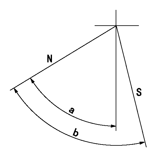
N:Pump normal
S:Stop the pump.
----------
----------
a=60deg+-5deg b=73deg+-3deg
----------
----------
a=60deg+-5deg b=73deg+-3deg
Timing setting
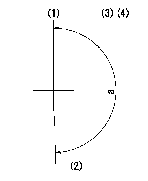
(1)Pump vertical direction
(2)Position of "Z" mark at the No 1 cylinder's beginning of injection (governor side)
(3)B.T.D.C.: aa
(4)-
----------
aa=10deg
----------
a=(170deg)
----------
aa=10deg
----------
a=(170deg)
Information:
Example of Pulse Width Modulation SignalsRated Fuel Position("Rated Fuel Pos" on ECAP) - this indicates the maximum allowable fuel position (longest injection pulse). It will produce rated power for this engine configuration.Reference VoltageA regulated voltage supplied by the ECM to a sensor. The reference voltage is used by the sensor to generate a signal voltage.Remote Mounted Throttle Position SensorThis sensor measures pedal position and sends a signal to the ECM. The sensor is mounted off of the throttle pedal assembly, usually near the fire wall in the engine compartment (not the cab). The throttle pedal is connected through an adjustable linkage to this pedal. See Pedal Mounted Throttle Position Sensor.Retarder Enable SignalThe retarder enable signal interfaces the ECM to the engine retarder. This will prohibit operation of the engine brake during undesirable engine operating conditions (such as while the engine is being fueled).SensorA device used to detect and convert a change in pressure, temperature, or mechanical movement into an electrical signal.Service Program ModuleA software program on a factory programmable computer chip, designed to adapt an ECAP or DDT to a specific application.Short CircuitA condition where an electrical circuit is unintentionally connected to an undesirable point. Example: a wire which rubs against a vehicle frame until it wears off its insulation and makes electrical contact with the frame.SignalA voltage or waveform used to transmit information typically from a sensor to the ECM.Speed "burp"A sudden brief change in engine speed.SubsystemAs used here, it is a part of the 3176 System that relates to a particular function, for instance: throttle subsystem, etc.Supply VoltageA constant voltage supplied to a component to provide electrical power for its operation. It may be generated by the ECM, or it may be vehicle battery voltage supplied by the vehicle wiring. "T" HarnessA test harness designed to permit normal circuit operation while measuring voltages, typically inserted between the two ends of a connector.Throttle PositionThe ECM's interpretation of the signal from the Throttle Position Sensor.Throttle Position SensorAn electronic sensor which is connected to the accelerator pedal and sends a Pulse Width Modulated signal to the ECM.Total TattletaleTotal number of changes to all Customer Specified Parameters.TransducerA device which converts a mechanical signal to an electrical signalTransducer ModuleA sealed unit mounted mounted on one end of the ECM, which contains the Boost Pressure Sensor and Atmospheric Pressure Sensor (if equipped), and protective signal conditioning circuitry.Vehicle Speed BufferA device used to condition and amplify the output of the vehicle speed sensor.Vehicle Speed SensorAn electromagnetic pickup that measures vehicle speed from the rotation of gear teeth in the drive train of the vehicle.Warning LampUsed to warn the operator of the presence of a Caterpillar Engine Protection detected problem.
