Information injection-pump assembly
ZEXEL
106891-1270
1068911270
ISUZU
1156025243
1156025243
Rating:
Service parts 106891-1270 INJECTION-PUMP ASSEMBLY:
1.
_
6.
COUPLING PLATE
7.
COUPLING PLATE
8.
_
9.
_
11.
Nozzle and Holder
1-15300-204-1
12.
Open Pre:MPa(Kqf/cm2)
15.7{160}/22.1{225}

15.
NOZZLE SET
Include in #1:
106891-1270
as INJECTION-PUMP ASSEMBLY
Cross reference number
ZEXEL
106891-1270
1068911270
ISUZU
1156025243
1156025243
Zexel num
Bosch num
Firm num
Name
Calibration Data:
Adjustment conditions
Test oil
1404 Test oil ISO4113 or {SAEJ967d}
1404 Test oil ISO4113 or {SAEJ967d}
Test oil temperature
degC
40
40
45
Nozzle and nozzle holder
105780-8140
Bosch type code
EF8511/9A
Nozzle
105780-0000
Bosch type code
DN12SD12T
Nozzle holder
105780-2080
Bosch type code
EF8511/9
Opening pressure
MPa
17.2
Opening pressure
kgf/cm2
175
Injection pipe
Outer diameter - inner diameter - length (mm) mm 8-3-600
Outer diameter - inner diameter - length (mm) mm 8-3-600
Overflow valve (drive side)
134424-4020
Overflow valve opening pressure (drive side)
kPa
255
221
289
Overflow valve opening pressure (drive side)
kgf/cm2
2.6
2.25
2.95
Overflow valve (governor side)
134424-2720
Overflow valve opening pressure (governor side)
kPa
255
221
289
Overflow valve opening pressure (governor side)
kgf/cm2
2.6
2.25
2.95
Tester oil delivery pressure
kPa
157
157
157
Tester oil delivery pressure
kgf/cm2
1.6
1.6
1.6
Direction of rotation (viewed from drive side)
Right R
Right R
Injection timing adjustment
Direction of rotation (viewed from drive side)
Right R
Right R
Injection order
1-8-7-3-
6-5-4-2
Pre-stroke
mm
4.2
4.17
4.23
Rack position
Point A R=A
Point A R=A
Beginning of injection position
Governor side NO.1
Governor side NO.1
Difference between angles 1
Cal 1-8 deg. 45 44.75 45.25
Cal 1-8 deg. 45 44.75 45.25
Difference between angles 2
Cal 1-7 deg. 90 89.75 90.25
Cal 1-7 deg. 90 89.75 90.25
Difference between angles 3
Cal 1-3 deg. 135 134.75 135.25
Cal 1-3 deg. 135 134.75 135.25
Difference between angles 4
Cal 1-6 deg. 180 179.75 180.25
Cal 1-6 deg. 180 179.75 180.25
Difference between angles 5
Cal 1-5 deg. 225 224.75 225.25
Cal 1-5 deg. 225 224.75 225.25
Difference between angles 6
Cal 1-4 deg. 270 269.75 270.25
Cal 1-4 deg. 270 269.75 270.25
Difference between angles 7
Cyl.1-2 deg. 315 314.75 315.25
Cyl.1-2 deg. 315 314.75 315.25
Injection quantity adjustment
Adjusting point
A
Rack position
8.5
Pump speed
r/min
800
800
800
Average injection quantity
mm3/st.
110
108.5
111.5
Max. variation between cylinders
%
0
-2
2
Basic
*
Fixing the lever
*
Injection quantity adjustment_02
Adjusting point
B
Rack position
8.8
Pump speed
r/min
500
500
500
Average injection quantity
mm3/st.
111.6
109.6
113.6
Fixing the lever
*
Injection quantity adjustment_03
Adjusting point
C
Rack position
7.9
Pump speed
r/min
1150
1150
1150
Average injection quantity
mm3/st.
117.4
115.4
119.4
Fixing the lever
*
Injection quantity adjustment_04
Adjusting point
D
Rack position
4.9+-0.5
Pump speed
r/min
225
225
225
Average injection quantity
mm3/st.
8.8
7.5
10.1
Max. variation between cylinders
%
0
-13
13
Fixing the rack
*
Timer adjustment
Pump speed
r/min
600--
Advance angle
deg.
0
0
0
Load
4/4
Remarks
Start
Start
Timer adjustment_02
Pump speed
r/min
550
Advance angle
deg.
0.3
Load
4/4
Timer adjustment_03
Pump speed
r/min
800+-30
Advance angle
deg.
2
1.5
2.5
Load
4/4
Timer adjustment_04
Pump speed
r/min
900
Advance angle
deg.
2
1.5
2.5
Load
3/4
Timer adjustment_05
Pump speed
r/min
1150
Advance angle
deg.
5.5
5
6
Load
4/4
Remarks
Finish
Finish
Test data Ex:
Governor adjustment
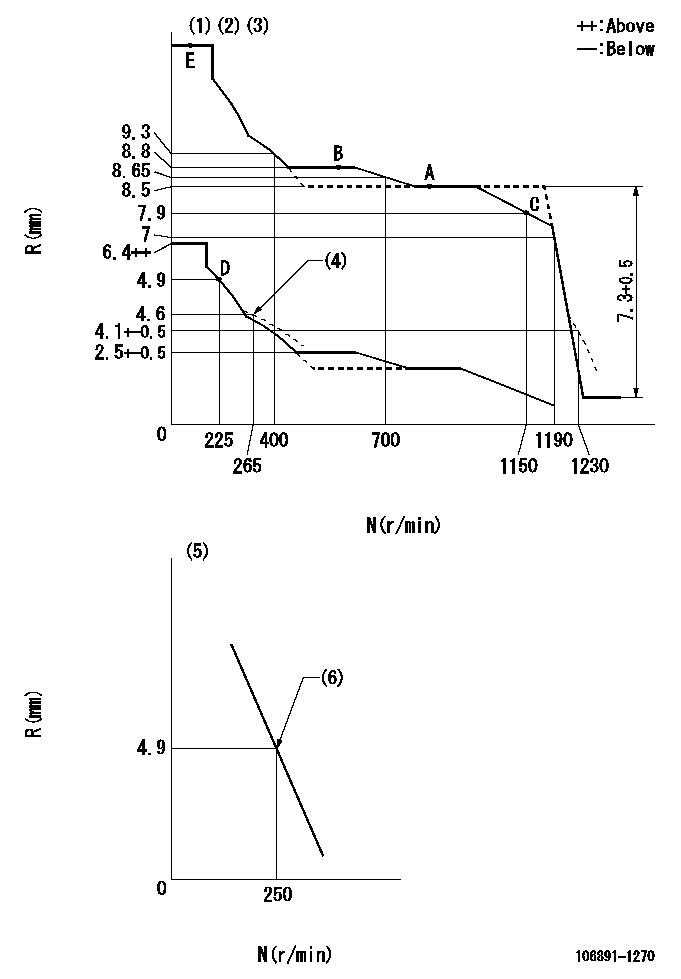
N:Pump speed
R:Rack position (mm)
(1)Lever ratio: RT
(2)Target shim dimension: TH
(3)Tolerance for racks not indicated: +-0.05mm.
(4)Damper spring setting
(5)Variable speed specification: idling adjustment
(6)Main spring setting
----------
RT=0.8 TH=2mm
----------
----------
RT=0.8 TH=2mm
----------
Speed control lever angle
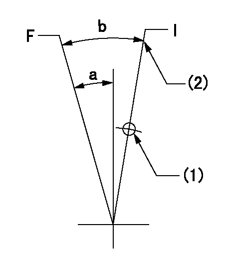
F:Full speed
I:Idle
(1)Use the hole at R = aa
(2)Stopper bolt setting
----------
aa=150mm
----------
a=6deg+-5deg b=(21deg)+-5deg
----------
aa=150mm
----------
a=6deg+-5deg b=(21deg)+-5deg
0000000901
F:Full load
I:Idle
(1)Use the hole at R = aa
(2)Stopper bolt setting
----------
aa=40mm
----------
a=10deg+-5deg b=34deg+-3deg
----------
aa=40mm
----------
a=10deg+-5deg b=34deg+-3deg
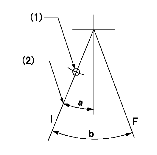
Stop lever angle

N:Pump normal
S:Stop the pump.
----------
----------
a=60deg+-5deg b=73deg+-5deg
----------
----------
a=60deg+-5deg b=73deg+-5deg
0000001501 LEVER
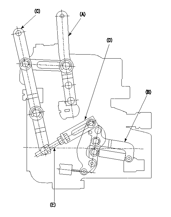
2-stage changeover lever adjustment
(A) Speed lever
(B) Load lever
(C) 2-stage changeover lever
(D) Link
(E) Bolt
1. Minimum-maximum speed specification adjustment (when running)
(1)After completing governor adjustment, hold the 2-stage changeover lever (C) so that the speed lever (A) contacts the full speed stopper.
(2)In this condition, the load lever is held in the idle position.
(3)Adjust bolt (E) so that the clearance between the pin underneath lever (C) and the end of the long groove in link (D) is L.
(4)Lock using the nut.
2. Variable speed specification adjustment (at operation)
(1)Hold the 2-stage changeover lever (C) so that the load lever (B) contacts the full load stopper. (When the load lever is equipped with a cancel mechanism, move it so that it contacts the stopper without canceling.)
(2)In this condition, confirm that the speed lever (A) moves from idle to full speed.
----------
L=1~2mm
----------
----------
L=1~2mm
----------
Timing setting

(1)Pump vertical direction
(2)Position of "Z" mark at the No 1 cylinder's beginning of injection (governor side)
(3)B.T.D.C.: aa (set timing)
(4)-
----------
aa=8deg
----------
a=(180deg)
----------
aa=8deg
----------
a=(180deg)
Information:
1. Remove two bolts (1) and remove oil supply line (2). Remove two bolts (3), loosen hose clamp (4) and move drain tube (5) out of the way. 2. Remove four nuts (6). Remove the turbocharger. The following steps are for the installation of the turbocharger.3. Apply 5P3931 Anti-Seize to turbocharger mounting studs. Position turbocharger gasket and turbocharger. Install four nuts (6). Tighten nuts to a torque of 55 5 N m (40 4 lb ft).4. Position drain tube with gasket and install bolts (3), then tighten hose clamp (4). Position oil supply line (2) with gasket and install bolts (1).Disassemble & Assemble Turbocharger
Start By:a. remove turbocharger 1. Place turbocharger in tooling (A). Put alignment marks on all the housings. Loosen clamp (1) and remove housing (2). 2. Loosen clamp (3) and remove cartridge assembly (4). 3. Place cartridge assembly (4) in tooling (B).
Use a 5S9566 Sliding T-Wrench and a universal socket to remove nut (5). Do not bend or add stress to the shaft when nut (5) is loosened or tightened.
4. Remove nut (5) and remove compressor wheel (6).5. Remove snap ring (7), then use two screw drivers and remove adapter plate (8). Remove O-ring seal (9) and inspect.6. Remove and inspect bushing and seal (10).7. Remove oil deflector (11) and thrust ring (12).8. Remove bearing (13), sleeve (14) and thrust ring (15).9. Lift housing assembly (19) off of shaft and wheel (20).10. Use snap ring pliers and remove wrap around snap ring (16), then remove double bushing (17).11. Remove seal ring (21) and backplate (18).12. Check all parts of the turbocharger for damage. If any parts are damaged, use new parts for replacement. See Special Instructions Form No. SMHS6854 for turbocharger reconditioning. Also, see Guidelines For Reusable Parts, Form No. SEBF8018. The following steps are for the assembly of the turbocharger.13. Make sure that all the oil passages in the turbocharger cartridge housing are clean and free of dirt and foreign material. Do not put oil on any parts of the turbocharger until after the compressor wheel has been assembled, put clean engine oil into the oil inlet of the turbocharger.14. With shaft and wheel (20) in tooling (B), install seal (21).15. Install double bushing (17) into housing (19) and install wrap around snap ring (16). Position housing assembly (19) onto shaft and wheel (20).16. Install thrust ring (15), bearing (13), sleeve (14) and thrust ring (12). Install oil deflector (11) then bushing and seal (10).17. With oil seal (9) in place, position adapter plate (8) and install snap ring (7).
Do not bend or add stress to the shaft when nut (5) is tightened.
18. Install compressor wheel (6) on the shaft. Put one drop of 9S2365 Retaining Compound on the threads of the shaft. Install nut (5) and torque it to 14.4 0.5 N m (144 5 lb in).19. Remove cartridge assembly (4) from tooling (B) and install it into the housing on tooling (A). Align marks and tighten clamp (3).20. Install