Information injection-pump assembly
ZEXEL
106891-1232
1068911232
ISUZU
1156021782
1156021782
Rating:
Service parts 106891-1232 INJECTION-PUMP ASSEMBLY:
1.
_
6.
COUPLING PLATE
7.
COUPLING PLATE
8.
_
9.
_
11.
Nozzle and Holder
1-15300-204-1
12.
Open Pre:MPa(Kqf/cm2)
15.7{160}/22.1{225}
15.
NOZZLE SET
Include in #1:
106891-1232
as INJECTION-PUMP ASSEMBLY
Cross reference number
ZEXEL
106891-1232
1068911232
ISUZU
1156021782
1156021782
Zexel num
Bosch num
Firm num
Name
Calibration Data:
Adjustment conditions
Test oil
1404 Test oil ISO4113 or {SAEJ967d}
1404 Test oil ISO4113 or {SAEJ967d}
Test oil temperature
degC
40
40
45
Nozzle and nozzle holder
105780-8140
Bosch type code
EF8511/9A
Nozzle
105780-0000
Bosch type code
DN12SD12T
Nozzle holder
105780-2080
Bosch type code
EF8511/9
Opening pressure
MPa
17.2
Opening pressure
kgf/cm2
175
Injection pipe
Outer diameter - inner diameter - length (mm) mm 8-3-600
Outer diameter - inner diameter - length (mm) mm 8-3-600
Overflow valve (drive side)
134424-4020
Overflow valve opening pressure (drive side)
kPa
255
221
289
Overflow valve opening pressure (drive side)
kgf/cm2
2.6
2.25
2.95
Overflow valve (governor side)
134424-2720
Overflow valve opening pressure (governor side)
kPa
255
221
289
Overflow valve opening pressure (governor side)
kgf/cm2
2.6
2.25
2.95
Tester oil delivery pressure
kPa
157
157
157
Tester oil delivery pressure
kgf/cm2
1.6
1.6
1.6
Direction of rotation (viewed from drive side)
Right R
Right R
Injection timing adjustment
Direction of rotation (viewed from drive side)
Right R
Right R
Injection order
1-8-7-3-
6-5-4-2
Pre-stroke
mm
4.2
4.17
4.23
Rack position
Point A R=A
Point A R=A
Beginning of injection position
Governor side NO.1
Governor side NO.1
Difference between angles 1
Cal 1-8 deg. 45 44.75 45.25
Cal 1-8 deg. 45 44.75 45.25
Difference between angles 2
Cal 1-7 deg. 90 89.75 90.25
Cal 1-7 deg. 90 89.75 90.25
Difference between angles 3
Cal 1-3 deg. 135 134.75 135.25
Cal 1-3 deg. 135 134.75 135.25
Difference between angles 4
Cal 1-6 deg. 180 179.75 180.25
Cal 1-6 deg. 180 179.75 180.25
Difference between angles 5
Cal 1-5 deg. 225 224.75 225.25
Cal 1-5 deg. 225 224.75 225.25
Difference between angles 6
Cal 1-4 deg. 270 269.75 270.25
Cal 1-4 deg. 270 269.75 270.25
Difference between angles 7
Cyl.1-2 deg. 315 314.75 315.25
Cyl.1-2 deg. 315 314.75 315.25
Injection quantity adjustment
Adjusting point
A
Rack position
8.5
Pump speed
r/min
800
800
800
Average injection quantity
mm3/st.
110
108.5
111.5
Max. variation between cylinders
%
0
-2
2
Basic
*
Fixing the lever
*
Injection quantity adjustment_02
Adjusting point
B
Rack position
8.8
Pump speed
r/min
500
500
500
Average injection quantity
mm3/st.
111.6
109.6
113.6
Fixing the lever
*
Injection quantity adjustment_03
Adjusting point
C
Rack position
7.9
Pump speed
r/min
1150
1150
1150
Average injection quantity
mm3/st.
117.4
115.4
119.4
Fixing the lever
*
Injection quantity adjustment_04
Adjusting point
D
Rack position
4.9+-0.5
Pump speed
r/min
225
225
225
Average injection quantity
mm3/st.
8.8
7.5
10.1
Max. variation between cylinders
%
0
-13
13
Fixing the rack
*
Timer adjustment
Pump speed
r/min
600--
Advance angle
deg.
0
0
0
Load
4/4
Remarks
Start
Start
Timer adjustment_02
Pump speed
r/min
550
Advance angle
deg.
0.3
Load
4/4
Timer adjustment_03
Pump speed
r/min
800+-30
Advance angle
deg.
2
1.5
2.5
Load
4/4
Timer adjustment_04
Pump speed
r/min
900
Advance angle
deg.
2
1.5
2.5
Load
3/4
Timer adjustment_05
Pump speed
r/min
1150
Advance angle
deg.
5.5
5
6
Load
4/4
Remarks
Finish
Finish
Test data Ex:
Governor adjustment
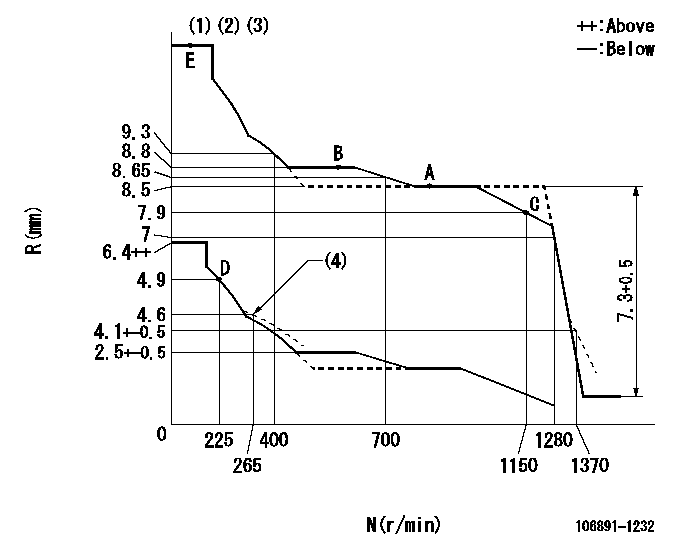
N:Pump speed
R:Rack position (mm)
(1)Lever ratio: RT
(2)Target shim dimension: TH
(3)Tolerance for racks not indicated: +-0.05mm.
(4)Damper spring setting
----------
RT=0.8 TH=2mm
----------
----------
RT=0.8 TH=2mm
----------
Speed control lever angle

F:Full speed
----------
----------
a=7deg+-5deg
----------
----------
a=7deg+-5deg
0000000901
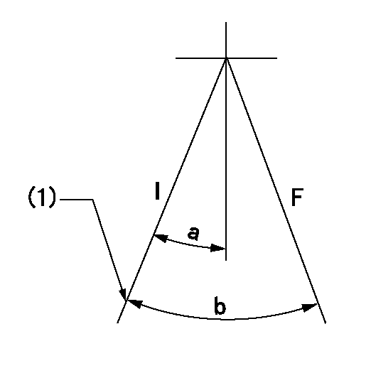
F:Full load
I:Idle
(1)Stopper bolt setting
----------
----------
a=10deg+-5deg b=34deg+-3deg
----------
----------
a=10deg+-5deg b=34deg+-3deg
Stop lever angle
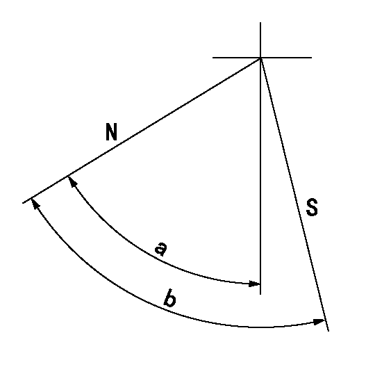
N:Pump normal
S:Stop the pump.
----------
----------
a=60deg+-5deg b=73deg+-5deg
----------
----------
a=60deg+-5deg b=73deg+-5deg
Timing setting
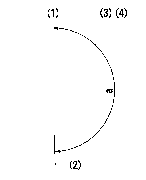
(1)Pump vertical direction
(2)Position of "Z" mark at the No 1 cylinder's beginning of injection (governor side)
(3)B.T.D.C.: aa (set timing)
(4)-
----------
aa=8deg
----------
a=(180deg)
----------
aa=8deg
----------
a=(180deg)
Information:
1. Remove four bolts and shield (1). Remove two bolts and screen (2). Disconnect ground strap (3) from the generator mounting bracket. Remove two generator mounting bolts (4). 2. Loosen front engine mounting bolts (5) to provide clearance to raise the rear of the engine. 3. Attach a hoist to generator (6). Raise the generator and the engine so the generator mounting pads are off of the supports. Put blocks under the flywheel housing to support the rear of the engine as shown. 4. Remove bolts (7) that hold fan (9) to the flywheel. Remove bolts (8) that hold the generator housing to the flywheel housing and remove the generator. The weight of the generator is approximately 1130 kg (2500 lb.).Connection Of Engine And Generator (Prime)
The following procudure applies to the 3406B Standby Generator also. 1. Remove the protection material (compound) from the flywheel pilot bore (10) and from the surface (11) that makes contact with the coupling. All contact surfaces of the engine, coupling and generator must be completely clean. 2. Install tooling (A) as shown on the front of the engine with the tip of the indicator on the face of crankshaft pulley (12). Use a bar between the flywheel and flywheel housing to push the crankshaft toward the flywheel to remove all end play. Put the dial indicator in the "zero" position. Move the crankshaft to its most forward position, and make a record of the Total Indicator Reading (TIR). The TIR is the end play of the crankshaft. 3. Put plate assembly (13) in position in the bore of the flywheel to check for clearance. There must be clearance between the outside diameter of the plate assembly (13) and the inside diameter of the bore in the flywheel.
Damage to the engine and/or generator can be the result if the electric set is run with a plate assembly that does not have this clearance.
4. Install full shim pack (14) and plate assembly (13) on the generator with bolts (15).5. Install a guide bolt in the flywheel. Put the generator in position on the engine, and install bolts (7) and (8).6. Use tooling (A) to check crankshaft end play. Do not use force to hold the crankshaft in position. Remove the generator. Remove only enough shims to get the original amount of end play as shown in Step 2. The minimum crankshaft end play should be 0.15 mm (0.006 in.).7. Install the generator and check the crankshaft end play again. If the end play is correct, attach a hoist to the generator and remove the blocks from under the flywheel housing.8. Lower the generator on to the supports and install bolts (4). Connect ground strap (3) to the generator. Install screen (2) and shield (1).9. Tighten fron engine mounting bolts (5).End By:a. install control panel enclosure
