Information injection-pump assembly
BOSCH
9 400 618 534
9400618534
ZEXEL
106876-2041
1068762041
MITSUBISHI
ME441240
me441240

Rating:
Cross reference number
BOSCH
9 400 618 534
9400618534
ZEXEL
106876-2041
1068762041
MITSUBISHI
ME441240
me441240
Zexel num
Bosch num
Firm num
Name
106876-2041
9 400 618 534
ME441240 MITSUBISHI
INJECTION-PUMP ASSEMBLY
8DC9TC K 14CD INJECTION PUMP ASSY PE8P PE
8DC9TC K 14CD INJECTION PUMP ASSY PE8P PE
Calibration Data:
Adjustment conditions
Test oil
1404 Test oil ISO4113 or {SAEJ967d}
1404 Test oil ISO4113 or {SAEJ967d}
Test oil temperature
degC
40
40
45
Nozzle and nozzle holder
105780-8140
Bosch type code
EF8511/9A
Nozzle
105780-0000
Bosch type code
DN12SD12T
Nozzle holder
105780-2080
Bosch type code
EF8511/9
Opening pressure
MPa
17.2
Opening pressure
kgf/cm2
175
Injection pipe
Outer diameter - inner diameter - length (mm) mm 8-3-600
Outer diameter - inner diameter - length (mm) mm 8-3-600
Overflow valve
131424-4620
Overflow valve opening pressure
kPa
255
221
289
Overflow valve opening pressure
kgf/cm2
2.6
2.25
2.95
Tester oil delivery pressure
kPa
157
157
157
Tester oil delivery pressure
kgf/cm2
1.6
1.6
1.6
Direction of rotation (viewed from drive side)
Right R
Right R
Injection timing adjustment
Direction of rotation (viewed from drive side)
Right R
Right R
Injection order
1-2-7-3-
4-5-6-8
Pre-stroke
mm
4.8
4.75
4.85
Beginning of injection position
Governor side NO.1
Governor side NO.1
Difference between angles 1
Cyl.1-2 deg. 45 44.5 45.5
Cyl.1-2 deg. 45 44.5 45.5
Difference between angles 2
Cal 1-7 deg. 90 89.5 90.5
Cal 1-7 deg. 90 89.5 90.5
Difference between angles 3
Cal 1-3 deg. 135 134.5 135.5
Cal 1-3 deg. 135 134.5 135.5
Difference between angles 4
Cal 1-4 deg. 180 179.5 180.5
Cal 1-4 deg. 180 179.5 180.5
Difference between angles 5
Cal 1-5 deg. 225 224.5 225.5
Cal 1-5 deg. 225 224.5 225.5
Difference between angles 6
Cal 1-6 deg. 270 269.5 270.5
Cal 1-6 deg. 270 269.5 270.5
Difference between angles 7
Cal 1-8 deg. 315 314.5 315.5
Cal 1-8 deg. 315 314.5 315.5
Injection quantity adjustment
Adjusting point
A
Rack position
11.3
Pump speed
r/min
800
800
800
Average injection quantity
mm3/st.
161
158
164
Max. variation between cylinders
%
0
-3
3
Basic
*
Fixing the lever
*
Boost pressure
kPa
61.3
61.3
Boost pressure
mmHg
460
460
Injection quantity adjustment_02
Adjusting point
B
Rack position
5.6+-0.5
Pump speed
r/min
275
275
275
Average injection quantity
mm3/st.
15.5
12.9
18.1
Max. variation between cylinders
%
0
-15
15
Fixing the rack
*
Boost pressure
kPa
0
0
0
Boost pressure
mmHg
0
0
0
Boost compensator adjustment
Pump speed
r/min
500
500
500
Rack position
R1-1.3
Boost pressure
kPa
21.3
20
22.6
Boost pressure
mmHg
160
150
170
Boost compensator adjustment_02
Pump speed
r/min
500
500
500
Rack position
R1(11.3)
Boost pressure
kPa
48
41.3
54.7
Boost pressure
mmHg
360
310
410
Timer adjustment
Pump speed
r/min
950--
Advance angle
deg.
0
0
0
Remarks
Start
Start
Timer adjustment_02
Pump speed
r/min
900
Advance angle
deg.
0.5
Timer adjustment_03
Pump speed
r/min
1100
Advance angle
deg.
0.5
0
1
Timer adjustment_04
Pump speed
r/min
-
Advance angle
deg.
1
1
1
Remarks
Measure the actual speed, stop
Measure the actual speed, stop
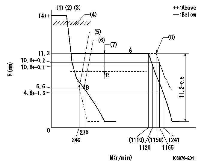
Test data Ex:
Governor adjustment

N:Pump speed
R:Rack position (mm)
(1)Notch fixed: K
(2)Tolerance for racks not indicated: +-0.05mm.
(3)Torque spring does not operate.
(4)Excess fuel lever setting: EXL (at boost pressure 0)
(5)Main spring setting
(6)Set idle sub-spring
(7)Boost compensator stroke: BCL
(8)At delivery
----------
K=15 EXL=13++mm BCL=1.3+-0.1mm
----------
----------
K=15 EXL=13++mm BCL=1.3+-0.1mm
----------
Speed control lever angle

F:Full speed
I:Idle
(1)Stopper bolt setting
(2)At delivery
----------
----------
a=(11.5deg)+-5deg b=(28.5deg)+-5deg c=(2deg)
----------
----------
a=(11.5deg)+-5deg b=(28.5deg)+-5deg c=(2deg)
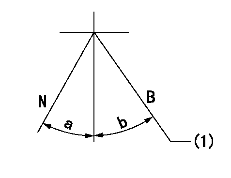
Stop lever angle

N:Pump normal
S:Stop the pump.
(1)Normal
----------
----------
a=19deg+-5deg b=46deg+-5deg
----------
----------
a=19deg+-5deg b=46deg+-5deg
0000001101

N:Normal
B:When boosted
(1)Rack position = at least aa (speed = bb; at boost pressure 0)
----------
aa=13mm bb=0r/min
----------
a=(10deg) b=(15deg)
----------
aa=13mm bb=0r/min
----------
a=(10deg) b=(15deg)
Timing setting

(1)Pump vertical direction
(2)Coupling's key groove position at No 1 cylinder's beginning of injection
(3)B.T.D.C.: aa
(4)-
----------
aa=14deg
----------
a=(40deg)
----------
aa=14deg
----------
a=(40deg)
Information:
P-302: Boost Pressure Sensor Calibration
The 3176 Boost Pressure Sensor must be calibrated for a zero boost condition with the engine OFF. Calibration is accomplished electronically without need for manual adjustments.The sensor must be recalibrated whenever the transducer module or ECM has been replaced. Incorrect sensor calibration may result in poor engine response or a Diagnostic Code 25 (Boost Pressure Sensor Fault) or a Diagnostic Code 42 (Check Sensor Calibration).Calibration Procedure:
1. Start engine and warm up to normal operating temperature, then turn key OFF.2. Turn key ON (engine off). The sensor will not calibrate if the engine is running.3. Select the Boost Sensor Calibration screen on the ECAP or DDT (see the Special Instructions included with the ECAP or DDT).4. Wait several seconds for the automatic calibration to occur. The screen will display "Calibrated" when finished.5. If the boost pressure sensor will not calibrate, follow P-225: Boost Pressure Sensor Test.P-303: Throttle Position Sensor Adjustment
The Throttle Position Sensor (TPS) is used to provide a throttle signal to the Electronic Control Module (ECM).Sensor output is a constant frequency signal whose pulse width varies with throttle position. This output signal is referred to as either "Duty Cycle" or a "Pulse Width Modulated (PWM)" signal and is expressed as a percentage. When correctly adjusted, the "Remote Mounted" TPS will produce a "Duty Cycle" signal of 15% to 20% at the low idle throttle position and 80% to 85% at the maximum throttle position. The "Pedal Mounted" TPS will produce a "Duty Cycle" of 10% to 22% at the low idle throttle position and 75% to 90% at the high idle throttle position. This signal is translated by the ECM into a "THROTTLE POSITION" signal of 3% at low idle and 100% at full throttle. Always use "DUTY CYCLE" for sensor adjustment.The Throttle Position Sensor may be one of two types. The "Remote-Mounted" TPS is about the size of a soft drink can and is connected to the throttle pedal by OEM-supplied linkage. It requires adjustment for correct operation (explained in this procedure). The "Pedal-Mounted" TPS is mounted directly to a specific style of throttle pedal and requires no adjustment, and in fact can not be adjusted (this procedure NOT needed). Both sensors provide the same type of signal to the ECM. Step 1. Inspect Throttle LinkageInspect the throttle linkage for loose, bent, broken, missing, or worn components. Also check for interference with the linkage or spring. The throttle linkage should work smoothly without excessive drag and return to a low idle position without assistance in less than 1 second. Repair linkage if needed.Step 2. Adjust At Low Idle PositionA. With key OFF-* Install the 40-Pin Breakout 'T' on the Vehicle Connector (J7/P7).* Connect Pulse Width Modulation Probe (from ECAP/DDT) to the Throttle Signal (Pin 40) of the Breakout 'T'. New Service Program Modules (SPM) allow the "Throttle Duty Cycle" to be read directly from the ECM without using the Pulse Width Modulation Probe. With the new SPM installed on the ECAP,
Have questions with 106876-2041?
Group cross 106876-2041 ZEXEL
Mitsubishi
Mitsubishi
Mitsubishi
106876-2041
9 400 618 534
ME441240
INJECTION-PUMP ASSEMBLY
8DC9TC
8DC9TC