Information injection-pump assembly
BOSCH
9 400 611 288
9400611288
ZEXEL
106876-2030
1068762030
MITSUBISHI
ME096389
me096389

Rating:
Service parts 106876-2030 INJECTION-PUMP ASSEMBLY:
1.
_
7.
COUPLING PLATE
8.
_
9.
_
11.
Nozzle and Holder
ME094539
12.
Open Pre:MPa(Kqf/cm2)
15.7{160}/21.6{220}
14.
NOZZLE
Include in #1:
106876-2030
as INJECTION-PUMP ASSEMBLY
Cross reference number
BOSCH
9 400 611 288
9400611288
ZEXEL
106876-2030
1068762030
MITSUBISHI
ME096389
me096389
Zexel num
Bosch num
Firm num
Name
106876-2030
9 400 611 288
ME096389 MITSUBISHI
INJECTION-PUMP ASSEMBLY
8DC9 K 14CD INJECTION PUMP ASSY PE8P PE
8DC9 K 14CD INJECTION PUMP ASSY PE8P PE
Calibration Data:
Adjustment conditions
Test oil
1404 Test oil ISO4113 or {SAEJ967d}
1404 Test oil ISO4113 or {SAEJ967d}
Test oil temperature
degC
40
40
45
Nozzle and nozzle holder
105780-8250
Bosch type code
1 688 901 101
Nozzle
105780-0120
Bosch type code
1 688 901 990
Nozzle holder
105780-2190
Opening pressure
MPa
20.7
Opening pressure
kgf/cm2
211
Injection pipe
Outer diameter - inner diameter - length (mm) mm 8-3-600
Outer diameter - inner diameter - length (mm) mm 8-3-600
Overflow valve
131425-0220
Overflow valve opening pressure
kPa
157
123
191
Overflow valve opening pressure
kgf/cm2
1.6
1.25
1.95
Tester oil delivery pressure
kPa
255
255
255
Tester oil delivery pressure
kgf/cm2
2.6
2.6
2.6
Direction of rotation (viewed from drive side)
Right R
Right R
Injection timing adjustment
Direction of rotation (viewed from drive side)
Right R
Right R
Injection order
1-2-7-3-
4-5-6-8
Pre-stroke
mm
3.9
3.85
3.95
Beginning of injection position
Governor side NO.1
Governor side NO.1
Difference between angles 1
Cyl.1-2 deg. 45 44.5 45.5
Cyl.1-2 deg. 45 44.5 45.5
Difference between angles 2
Cal 1-7 deg. 90 89.5 90.5
Cal 1-7 deg. 90 89.5 90.5
Difference between angles 3
Cal 1-3 deg. 135 134.5 135.5
Cal 1-3 deg. 135 134.5 135.5
Difference between angles 4
Cal 1-4 deg. 180 179.5 180.5
Cal 1-4 deg. 180 179.5 180.5
Difference between angles 5
Cal 1-5 deg. 225 224.5 225.5
Cal 1-5 deg. 225 224.5 225.5
Difference between angles 6
Cal 1-6 deg. 270 269.5 270.5
Cal 1-6 deg. 270 269.5 270.5
Difference between angles 7
Cal 1-8 deg. 315 314.5 315.5
Cal 1-8 deg. 315 314.5 315.5
Injection quantity adjustment
Adjusting point
-
Rack position
11.5
Pump speed
r/min
700
700
700
Each cylinder's injection qty
mm3/st.
115.5
112
119
Basic
*
Fixing the rack
*
Standard for adjustment of the maximum variation between cylinders
*
Injection quantity adjustment_02
Adjusting point
Z
Rack position
8+-0.5
Pump speed
r/min
430
430
430
Each cylinder's injection qty
mm3/st.
14
11.9
16.1
Fixing the rack
*
Standard for adjustment of the maximum variation between cylinders
*
Injection quantity adjustment_03
Adjusting point
A
Rack position
R1(11.5)
Pump speed
r/min
700
700
700
Average injection quantity
mm3/st.
115.5
114.5
116.5
Basic
*
Fixing the lever
*
Injection quantity adjustment_04
Adjusting point
B
Rack position
R1+1.2
Pump speed
r/min
1100
1100
1100
Average injection quantity
mm3/st.
123
119
127
Fixing the lever
*
Injection quantity adjustment_05
Adjusting point
C
Rack position
(R1-0.55
)
Pump speed
r/min
500
500
500
Average injection quantity
mm3/st.
113.5
109.5
117.5
Fixing the lever
*
Timer adjustment
Pump speed
r/min
880--
Advance angle
deg.
0
0
0
Remarks
Start
Start
Timer adjustment_02
Pump speed
r/min
830
Advance angle
deg.
0.5
Timer adjustment_03
Pump speed
r/min
1050
Advance angle
deg.
3
2.5
3.5
Remarks
Finish
Finish
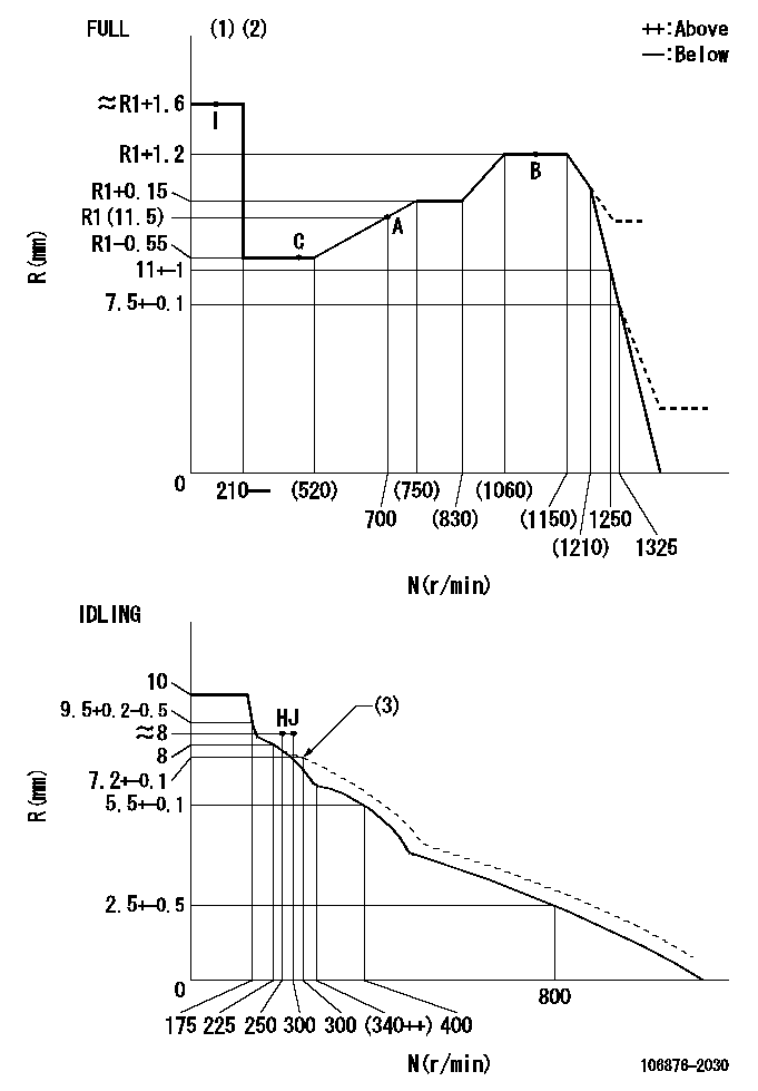
Test data Ex:
Governor adjustment

N:Pump speed
R:Rack position (mm)
(1)Torque cam stamping: T1
(2)Tolerance for racks not indicated: +-0.05mm.
(3)Damper spring setting
----------
T1=AC91
----------
----------
T1=AC91
----------
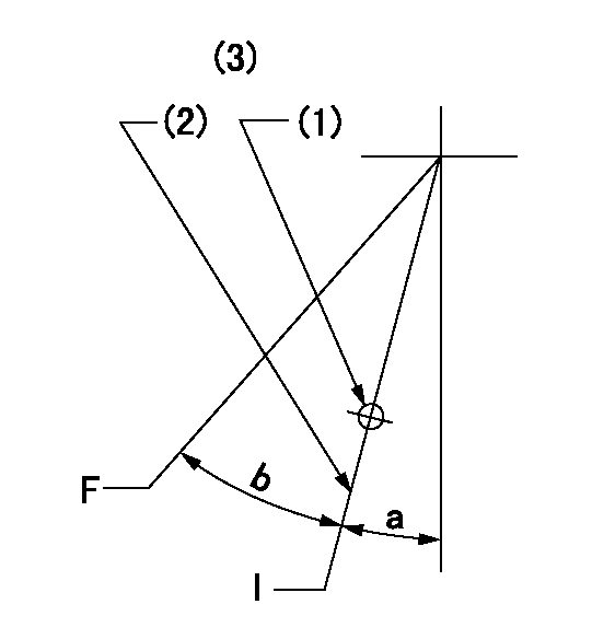
Speed control lever angle

F:Full speed
I:Idle
(1)Use the hole at R = aa
(2)Stopper bolt set position 'H'
(3)Viewed from feed pump side.
----------
aa=37.5mm
----------
a=32deg+-5deg b=35.5deg+-3deg
----------
aa=37.5mm
----------
a=32deg+-5deg b=35.5deg+-3deg
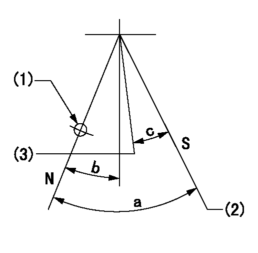
Stop lever angle

N:Pump normal
S:Stop the pump.
(1)Use the hole at R = aa
(2)Set the stopper bolt so that speed = bb and rack position = cc. (Confirm non-injection.)
(3)Normal engine position (equivalent to R = dd).
----------
aa=54mm bb=1100r/min cc=3+-0.3mm dd=17.5mm
----------
a=41deg+-5deg b=5.5deg+-5deg c=(31deg)
----------
aa=54mm bb=1100r/min cc=3+-0.3mm dd=17.5mm
----------
a=41deg+-5deg b=5.5deg+-5deg c=(31deg)
Timing setting

(1)Pump vertical direction
(2)Coupling's key groove position at No 1 cylinder's beginning of injection
(3)B.T.D.C.: aa
(4)-
----------
aa=12deg
----------
a=(40deg)
----------
aa=12deg
----------
a=(40deg)
Information:
P-104: Low Power/Poor Or No Response To Throttle
Probable root causes:
* Active diagnostic codes* Customer Specified Parameters (normal operation)* Throttle position signal* Boost pressure signal* Vehicle speed signal* Fuel supply* Air inlet or exhaust restrictions* Inlet air system leaksPerform the following tests in order:1. Troubleshoot any ACTIVE diagnostic codes.* Codes 31 or 36 limit engine speed to rpm at VSL* Codes 25 or 42 limit power or rpm or both* Code 32 limits engine speed to low idle* Code 56 may limit engine speed to low idle, depending on which parameter caused the code to be generated2. Verify that complaint is not normal (programmed parameter) operation.* Check vehicle speed limit, progressive shift parameters etc.3. Verify that engine has shifted out of Cold Mode4. P-211: Throttle Position Sensor Test4. P-225: Boost Pressure Sensor Test5. P-213: Vehicle Speed Signal Test6. Inspect fuel system components and check for correct fuel pressure.7. Check the air inlet and exhaust systems for restrictions, refer to 3176 Diesel Truck Engine, Form SENR4248, Mechanical Troubleshooting.8. Run PAR (Performance Analysis Report) TestP-105: Cruise Or PTO Does Not Function
Probable root causes:
* Active Diagnostic Codes* Customer Specified Parameters (normal operation)* Cruise/PTO Switches* Vehicle speed signalPerform the following tests in order:1. Troubleshoot any ACTIVE diagnostic codes.2. Check Customer Specified Parameters* High Cruise Limit and Low Cruise Limit* PTO Mode speed limit3. P-214: Cruise Control and PTO Switches Test4. P-215: Service Brake and Clutch Switches Test5. P-213: Vehicle Speed Signal TestP-110: Intermittent Engine Shutdowns
Use this procedure ONLY if the engine has shut down completely and had to be restarted using the key switch.Probable root causes:
* Battery power or ground to ECM (vehicle wiring).* Aftermarket engine protection devices [the 2YG (S/N) prefix 3176 Diesel Truck Engine does NOT have its own engine protection shutdown feature].* 3176 Engine wiring harness* Fuel supply* Engine Speed/Timing Sensor* ECM or Personality ModulePerform the following tests in order:1. Check external 3176 Harness and connectors (refer to P-201: Inspecting Electrical Connectors.2. Check for correct installation and operation of engine protection devices.3. Check for correct installation of J4/P4 (40 Pin-ECM connector).4. P-210: Electrical Power Supply Test.5. Check fuel lines for restrictions and fuel tanks for foreign objects which may block fuel supply.6. P-221: Engine Speed/Timing Sensor Test.7. P-220: ECM and Personality Module Test.P-111: Intermittent Low Power Or Power Cutouts
Use this procedure only if engine DOES NOT completely shut down (that is, it did NOT need to be restarted using the key switch).Probable root causes:
* Poor electrical connections* Battery power or ground to ECM (vehicle wiring)* Vehicle speed signal* Engine Speed/Timing Sensor* Fuel supply* Throttle Position Sensor* Cruise control switches* Service Brake and Clutch SwitchesPerform the following tests in order:1. Check external 3176 Harness and connectors (refer to P-201: Inspecting Electrical Connectors).2. P-210: Electrical Power Supply Test3. P-213: Vehicle Speed Signal Test4. P-221: Engine Speed/Timing Sensor Test5. Check fuel lines for restrictions and fuel tanks for foreign objects which may block fuel supply.6. P-211: Throttle Position Sensor Test.7. P-214: Cruise Control and PTO Switches Test.8. P-215: Service Brake and Clutch Switches
Probable root causes:
* Active diagnostic codes* Customer Specified Parameters (normal operation)* Throttle position signal* Boost pressure signal* Vehicle speed signal* Fuel supply* Air inlet or exhaust restrictions* Inlet air system leaksPerform the following tests in order:1. Troubleshoot any ACTIVE diagnostic codes.* Codes 31 or 36 limit engine speed to rpm at VSL* Codes 25 or 42 limit power or rpm or both* Code 32 limits engine speed to low idle* Code 56 may limit engine speed to low idle, depending on which parameter caused the code to be generated2. Verify that complaint is not normal (programmed parameter) operation.* Check vehicle speed limit, progressive shift parameters etc.3. Verify that engine has shifted out of Cold Mode4. P-211: Throttle Position Sensor Test4. P-225: Boost Pressure Sensor Test5. P-213: Vehicle Speed Signal Test6. Inspect fuel system components and check for correct fuel pressure.7. Check the air inlet and exhaust systems for restrictions, refer to 3176 Diesel Truck Engine, Form SENR4248, Mechanical Troubleshooting.8. Run PAR (Performance Analysis Report) TestP-105: Cruise Or PTO Does Not Function
Probable root causes:
* Active Diagnostic Codes* Customer Specified Parameters (normal operation)* Cruise/PTO Switches* Vehicle speed signalPerform the following tests in order:1. Troubleshoot any ACTIVE diagnostic codes.2. Check Customer Specified Parameters* High Cruise Limit and Low Cruise Limit* PTO Mode speed limit3. P-214: Cruise Control and PTO Switches Test4. P-215: Service Brake and Clutch Switches Test5. P-213: Vehicle Speed Signal TestP-110: Intermittent Engine Shutdowns
Use this procedure ONLY if the engine has shut down completely and had to be restarted using the key switch.Probable root causes:
* Battery power or ground to ECM (vehicle wiring).* Aftermarket engine protection devices [the 2YG (S/N) prefix 3176 Diesel Truck Engine does NOT have its own engine protection shutdown feature].* 3176 Engine wiring harness* Fuel supply* Engine Speed/Timing Sensor* ECM or Personality ModulePerform the following tests in order:1. Check external 3176 Harness and connectors (refer to P-201: Inspecting Electrical Connectors.2. Check for correct installation and operation of engine protection devices.3. Check for correct installation of J4/P4 (40 Pin-ECM connector).4. P-210: Electrical Power Supply Test.5. Check fuel lines for restrictions and fuel tanks for foreign objects which may block fuel supply.6. P-221: Engine Speed/Timing Sensor Test.7. P-220: ECM and Personality Module Test.P-111: Intermittent Low Power Or Power Cutouts
Use this procedure only if engine DOES NOT completely shut down (that is, it did NOT need to be restarted using the key switch).Probable root causes:
* Poor electrical connections* Battery power or ground to ECM (vehicle wiring)* Vehicle speed signal* Engine Speed/Timing Sensor* Fuel supply* Throttle Position Sensor* Cruise control switches* Service Brake and Clutch SwitchesPerform the following tests in order:1. Check external 3176 Harness and connectors (refer to P-201: Inspecting Electrical Connectors).2. P-210: Electrical Power Supply Test3. P-213: Vehicle Speed Signal Test4. P-221: Engine Speed/Timing Sensor Test5. Check fuel lines for restrictions and fuel tanks for foreign objects which may block fuel supply.6. P-211: Throttle Position Sensor Test.7. P-214: Cruise Control and PTO Switches Test.8. P-215: Service Brake and Clutch Switches
Have questions with 106876-2030?
Group cross 106876-2030 ZEXEL
Mitsubishi
Mitsubishi
106876-2030
9 400 611 288
ME096389
INJECTION-PUMP ASSEMBLY
8DC9
8DC9