Information injection-pump assembly
BOSCH
9 400 618 532
9400618532
ZEXEL
106876-2000
1068762000
MITSUBISHI
ME098778
me098778

Rating:
Service parts 106876-2000 INJECTION-PUMP ASSEMBLY:
1.
_
2.
FUEL INJECTION PUMP
7.
COUPLING PLATE
8.
_
9.
_
11.
Nozzle and Holder
12.
Open Pre:MPa(Kqf/cm2)
17.7(180)/21.6(220)
15.
NOZZLE SET
Include in #1:
106876-2000
as INJECTION-PUMP ASSEMBLY
Cross reference number
BOSCH
9 400 618 532
9400618532
ZEXEL
106876-2000
1068762000
MITSUBISHI
ME098778
me098778
Zexel num
Bosch num
Firm num
Name
106876-2000
9 400 618 532
ME098778 MITSUBISHI
INJECTION-PUMP ASSEMBLY
8DC9TC K 14CD INJECTION PUMP ASSY PE8P PE
8DC9TC K 14CD INJECTION PUMP ASSY PE8P PE
Calibration Data:
Adjustment conditions
Test oil
1404 Test oil ISO4113 or {SAEJ967d}
1404 Test oil ISO4113 or {SAEJ967d}
Test oil temperature
degC
40
40
45
Nozzle and nozzle holder
105780-8140
Bosch type code
EF8511/9A
Nozzle
105780-0000
Bosch type code
DN12SD12T
Nozzle holder
105780-2080
Bosch type code
EF8511/9
Opening pressure
MPa
17.2
Opening pressure
kgf/cm2
175
Injection pipe
Outer diameter - inner diameter - length (mm) mm 8-3-600
Outer diameter - inner diameter - length (mm) mm 8-3-600
Overflow valve
131424-4620
Overflow valve opening pressure
kPa
255
221
289
Overflow valve opening pressure
kgf/cm2
2.6
2.25
2.95
Tester oil delivery pressure
kPa
157
157
157
Tester oil delivery pressure
kgf/cm2
1.6
1.6
1.6
Direction of rotation (viewed from drive side)
Right R
Right R
Injection timing adjustment
Direction of rotation (viewed from drive side)
Right R
Right R
Injection order
1-2-7-3-
4-5-6-8
Pre-stroke
mm
4.8
4.75
4.85
Beginning of injection position
Governor side NO.1
Governor side NO.1
Difference between angles 1
Cyl.1-2 deg. 45 44.5 45.5
Cyl.1-2 deg. 45 44.5 45.5
Difference between angles 2
Cal 1-7 deg. 90 89.5 90.5
Cal 1-7 deg. 90 89.5 90.5
Difference between angles 3
Cal 1-3 deg. 135 134.5 135.5
Cal 1-3 deg. 135 134.5 135.5
Difference between angles 4
Cal 1-4 deg. 180 179.5 180.5
Cal 1-4 deg. 180 179.5 180.5
Difference between angles 5
Cal 1-5 deg. 225 224.5 225.5
Cal 1-5 deg. 225 224.5 225.5
Difference between angles 6
Cal 1-6 deg. 270 269.5 270.5
Cal 1-6 deg. 270 269.5 270.5
Difference between angles 7
Cal 1-8 deg. 315 314.5 315.5
Cal 1-8 deg. 315 314.5 315.5
Injection quantity adjustment
Adjusting point
A
Rack position
11.6
Pump speed
r/min
800
800
800
Average injection quantity
mm3/st.
165
162
168
Max. variation between cylinders
%
0
-3
3
Basic
*
Fixing the lever
*
Boost pressure
kPa
61.3
61.3
Boost pressure
mmHg
460
460
Injection quantity adjustment_02
Adjusting point
B
Rack position
5.7+-0.5
Pump speed
r/min
375
375
375
Average injection quantity
mm3/st.
19.5
16.9
22.1
Max. variation between cylinders
%
0
-15
15
Fixing the rack
*
Boost pressure
kPa
0
0
0
Boost pressure
mmHg
0
0
0
Boost compensator adjustment
Pump speed
r/min
500
500
500
Rack position
R1-1.3
Boost pressure
kPa
21.3
20
22.6
Boost pressure
mmHg
160
150
170
Boost compensator adjustment_02
Pump speed
r/min
500
500
500
Rack position
R1(11.6)
Boost pressure
kPa
48
41.3
54.7
Boost pressure
mmHg
360
310
410
Timer adjustment
Pump speed
r/min
950--
Advance angle
deg.
0
0
0
Remarks
Start
Start
Timer adjustment_02
Pump speed
r/min
900
Advance angle
deg.
0.5
Timer adjustment_03
Pump speed
r/min
1100
Advance angle
deg.
0.5
0
1
Timer adjustment_04
Pump speed
r/min
-
Advance angle
deg.
1
1
1
Remarks
Measure the actual speed, stop
Measure the actual speed, stop
Test data Ex:
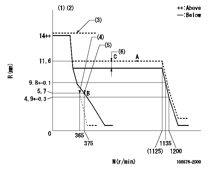
Governor adjustment

N:Pump speed
R:Rack position (mm)
(1)Target notch: K
(2)Tolerance for racks not indicated: +-0.05mm.
(3)With rack sensor (no limit): confirm at least Ra (confirm rack sensor output voltage of at least V1).
(4)Main spring setting
(5)Set idle sub-spring
(6)Boost compensator stroke: BCL
----------
K=7 RA=14mm V1=3.48V BCL=1.3+-0.1mm
----------
----------
K=7 RA=14mm V1=3.48V BCL=1.3+-0.1mm
----------
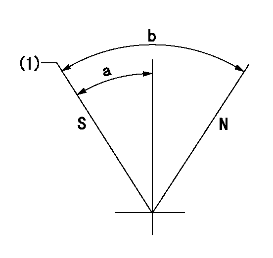
Speed control lever angle

F:Full speed
I:Idle
(1)Stopper bolt setting
----------
----------
a=25deg+-5deg b=5deg+-5deg
----------
----------
a=25deg+-5deg b=5deg+-5deg
Stop lever angle

N:Pump normal
S:Stop the pump.
(1)Pump speed aa and rack position bb (to be sealed at delivery)
----------
aa=0r/min bb=1-0.5mm
----------
a=35deg+-5deg b=70deg+-5deg
----------
aa=0r/min bb=1-0.5mm
----------
a=35deg+-5deg b=70deg+-5deg
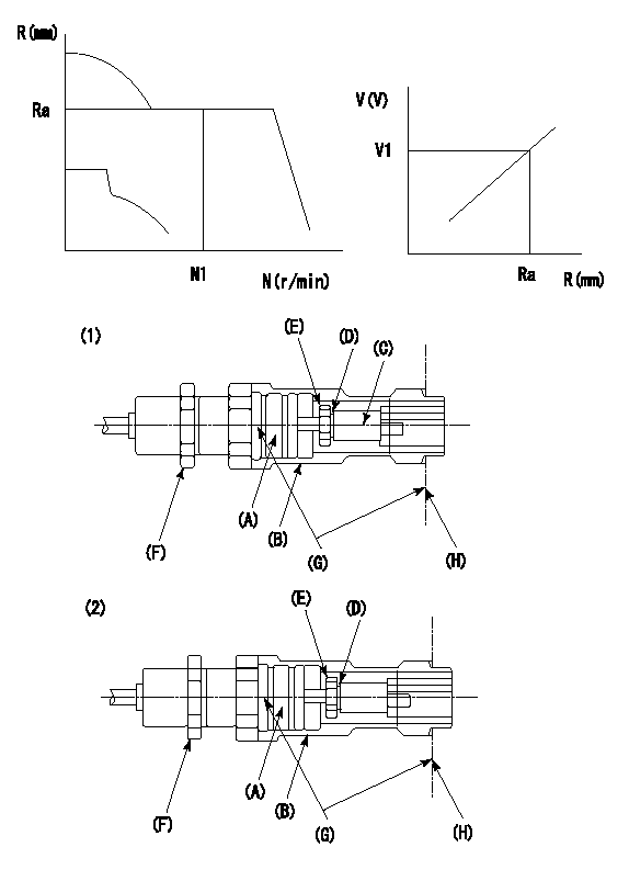
0000001501 RACK SENSOR

G:Red paint
H:Pump end face
P/N: part number of suitable shim
(1)Threaded type rack block
(2)Welded type rack block
Rack sensor adjustment
1. Threaded type rack sensor (-5*20, P type, no TICS rack limit).
(1)Screw in the bobbin (A) until it contacts the joint (B).
(2)Fix the pump lever.
(3)At speed N1 and rack position Ra, adjust the amount that the bobbin is screwed in so that the amp's output voltage is V1.
(4)Fix using the nut (F).
(5)Affix the caution plate to the upper part of the joint (B).
(6)Apply (G) at two places.
Connecting part between the joint (B) and the nut (F)
Connecting part between the end surface of the pump (H) and the joint (B)
2. Range for screw-in adjustment between the bobbin (A) and the joint (B) is 9 threads.
Screw in to the end from (the position where the bobbin (A) is rotated 9 turns).
Speed N1, rack position Ra, output voltage V1, rack sensor supply voltage 5+-0.01 (V)
----------
Ra=11.6mm N1=800r/min V1=3+-0.01V
----------
----------
Ra=11.6mm N1=800r/min V1=3+-0.01V
----------
Timing setting

(1)Pump vertical direction
(2)Coupling's key groove position at No 1 cylinder's beginning of injection
(3)B.T.D.C.: aa
(4)-
----------
aa=14deg
----------
a=(40deg)
----------
aa=14deg
----------
a=(40deg)
Information:
Cruise Control On/Off Input Circuit
The cruise control (CC) and power take-off (PTO) ON/OFF input is an ordinary switch. With this switch in the ON position, it is possible to "activate" the cruise control or power take-off mode if other ECM programmed conditions are met.With this switch "open" (or OFF), the input line to the ECM will go to approximately 5 volts. With the switch "closed" (or ON), the input line to the ECM will go to 0 volts (ground).Cruise Control Set/Resume Input Circuit
The cruise control and power take-off set/resume is provided by a three position switch. The switch is used to SET vehicle speed or engine rpm. The function of each position of the switch is as follows:1) CENTER POSITION, the set/resume switch is "open" and all inputs are inactive.2) SET POSITION, after the switch is moved to the SET position and released, the ECM will maintain the existing engine rpm (determining vehicle speed) when the switch was released. If the engine is held in the SET position, the ECM will gradually increase engine rpm (determining vehicle speed) until the switch is released.3) RESUME POSITION, if cruise is deactivated by application of the clutch or service brake, and the switch is then moved to the RESUME position and released, the cruise (PTO) mode is reactivated to the last setting. If the switch is held in the RESUME position, the ECM will gradually decrease engine rpm (determining vehicle speed) until the switch is released.With this switch "open" (or OFF), the input line to the ECM will go to approximately 5 volts. With the switch "closed" (or ON), the input line to the ECM will go to 0 volts (ground).Vehicle Switches Input Circuits
The brake switch is used to deactivate the cruise or PTO modes when the vehicle service brakes are applied. The brake switch is also used to activate the retarder enable output if the service brakes are applied while in cruise mode.The clutch switch is used to deactivate the cruise or PTO modes when the clutch pedal is pressed. The clutch switch is used to DEACTIVATE the retarder enable circuit.With this switch "open" (or OFF), the input line to the EMC will go to approximately 5 volts. With the switch "closed" (or ON), the input line to the EMC will go to 0 volts (ground).Fuel Pressure Input Circuit
Fuel pressure is monitored after the filter by the fuel pressure sensor which is located on the fuel filter housing. The 5 Volt DC operating voltage for this sensor is supplied by the ECM. The output of the fuel pressure sensor is a .5 to 4.5 Volts DC signal. The voltage is dependent upon fuel pressure and is interpreted by the ECM as fuel pressure. If fuel pressure is less than 445 kPa (65 psi) at rated rpm, the "check engine" light is turned on.Engine Electrical System
The electrical system can have three separate circuits: the charging circuit, the starting circuit and the low amperage circuit. Some of the electrical system components are
Have questions with 106876-2000?
Group cross 106876-2000 ZEXEL
Mitsubishi
106876-2000
9 400 618 532
ME098778
INJECTION-PUMP ASSEMBLY
8DC9TC
8DC9TC