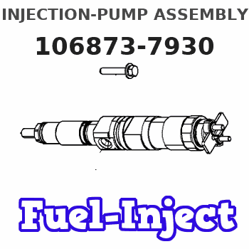
Information injection-pump assembly
BOSCH
9 400 618 526
9400618526
ZEXEL
106873-7930
1068737930
MITSUBISHI
ME095027
me095027
Rating:
Cross reference number
BOSCH
9 400 618 526
9400618526
ZEXEL
106873-7930
1068737930
MITSUBISHI
ME095027
me095027
Zexel num
Bosch num
Firm num
Name
106873-7930
9 400 618 526
ME095027 MITSUBISHI
INJECTION-PUMP ASSEMBLY
8DC91 K 14CD INJECTION PUMP ASSY PE8P PE
8DC91 K 14CD INJECTION PUMP ASSY PE8P PE
Calibration Data:
Adjustment conditions
Test oil
1404 Test oil ISO4113 or {SAEJ967d}
1404 Test oil ISO4113 or {SAEJ967d}
Test oil temperature
degC
40
40
45
Nozzle and nozzle holder
105780-8140
Bosch type code
EF8511/9A
Nozzle
105780-0000
Bosch type code
DN12SD12T
Nozzle holder
105780-2080
Bosch type code
EF8511/9
Opening pressure
MPa
17.2
Opening pressure
kgf/cm2
175
Injection pipe
Outer diameter - inner diameter - length (mm) mm 8-3-600
Outer diameter - inner diameter - length (mm) mm 8-3-600
Overflow valve
134424-1320
Overflow valve opening pressure
kPa
157
123
191
Overflow valve opening pressure
kgf/cm2
1.6
1.25
1.95
Tester oil delivery pressure
kPa
157
157
157
Tester oil delivery pressure
kgf/cm2
1.6
1.6
1.6
Direction of rotation (viewed from drive side)
Right R
Right R
Injection timing adjustment
Direction of rotation (viewed from drive side)
Right R
Right R
Injection order
1-2-7-3-
4-5-6-8
Pre-stroke
mm
4.8
4.75
4.85
Beginning of injection position
Governor side NO.1
Governor side NO.1
Difference between angles 1
Cyl.1-2 deg. 45 44.5 45.5
Cyl.1-2 deg. 45 44.5 45.5
Difference between angles 2
Cal 1-7 deg. 90 89.5 90.5
Cal 1-7 deg. 90 89.5 90.5
Difference between angles 3
Cal 1-3 deg. 135 134.5 135.5
Cal 1-3 deg. 135 134.5 135.5
Difference between angles 4
Cal 1-4 deg. 180 179.5 180.5
Cal 1-4 deg. 180 179.5 180.5
Difference between angles 5
Cal 1-5 deg. 225 224.5 225.5
Cal 1-5 deg. 225 224.5 225.5
Difference between angles 6
Cal 1-6 deg. 270 269.5 270.5
Cal 1-6 deg. 270 269.5 270.5
Difference between angles 7
Cal 1-8 deg. 315 314.5 315.5
Cal 1-8 deg. 315 314.5 315.5
Injection quantity adjustment
Adjusting point
-
Rack position
9.5
Pump speed
r/min
700
700
700
Each cylinder's injection qty
mm3/st.
118
114.5
121.5
Basic
*
Fixing the rack
*
Standard for adjustment of the maximum variation between cylinders
*
Injection quantity adjustment_02
Adjusting point
C
Rack position
6.1+-0.5
Pump speed
r/min
225
225
225
Each cylinder's injection qty
mm3/st.
20
17
23
Fixing the rack
*
Standard for adjustment of the maximum variation between cylinders
*
Injection quantity adjustment_03
Adjusting point
A
Rack position
R1(9.5)
Pump speed
r/min
700
700
700
Average injection quantity
mm3/st.
118
117
119
Basic
*
Fixing the lever
*
Injection quantity adjustment_04
Adjusting point
B
Rack position
R1(9.5)
Pump speed
r/min
1100
1100
1100
Average injection quantity
mm3/st.
124
118.8
129.2
Difference in delivery
mm3/st.
10.4
10.4
10.4
Fixing the lever
*
Injection quantity adjustment_05
Adjusting point
E
Rack position
-
Pump speed
r/min
100
100
100
Average injection quantity
mm3/st.
145
105
185
Fixing the lever
*
Remarks
After startup boost setting
After startup boost setting
Timer adjustment
Pump speed
r/min
550--
Advance angle
deg.
0
0
0
Remarks
Start
Start
Timer adjustment_02
Pump speed
r/min
500
Advance angle
deg.
0.5
Timer adjustment_03
Pump speed
r/min
1100
Advance angle
deg.
5
4.5
5.5
Remarks
Finish
Finish
Test data Ex:
Governor adjustment
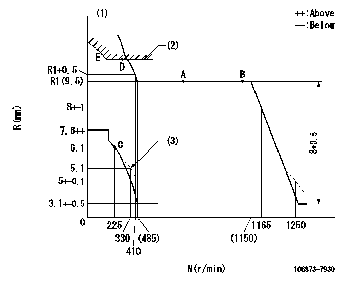
N:Pump speed
R:Rack position (mm)
(1)Tolerance for racks not indicated: +-0.05mm.
(2)Excess fuel setting for starting: SXL
(3)Damper spring setting
----------
SXL=10.2+-0.1mm
----------
----------
SXL=10.2+-0.1mm
----------
Speed control lever angle

F:Full speed
----------
----------
a=19.5deg+-5deg
----------
----------
a=19.5deg+-5deg
0000000901

F:Full load
I:Idle
(1)Stopper bolt setting
----------
----------
a=10deg+-5deg b=23.5deg+-3deg
----------
----------
a=10deg+-5deg b=23.5deg+-3deg
Stop lever angle
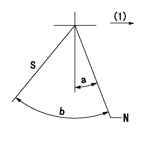
N:Pump normal
S:Stop the pump.
(1)Drive side
----------
----------
a=19.5deg+-5deg b=64deg+-5deg
----------
----------
a=19.5deg+-5deg b=64deg+-5deg
Timing setting

(1)Pump vertical direction
(2)Coupling's key groove position at No 1 cylinder's beginning of injection
(3)-
(4)-
----------
----------
a=(40deg)
----------
----------
a=(40deg)
Information:
1. Drain the coolant and oil from the engine.2. Remove bolt (1) and retainer (2) that hold the oil lines in the BrakeSaver control valve. 3. Disconnect oil lines (3) and (4) from the oil cooler. Remove oil lines (3) and (4) from the BrakeSaver control valve.4. Fasten a hoist to the oil cooler. 5. Remove two bolts (8) to disconnect elbow (10) from front bonnet (9). Remove two bolts (7) to disconnect front bonnet (9) from water pump.6. Remove four bolts (5) to disconnect the rear bonnet from the cylinder block. Disconnect bracket (12).7. Remove oil cooler (11), front bonnet (9) and rear bonnet (6) from the engine as a unit. The weight is approximately 54 kg (120 lb.).8. Make a separation of front bonnet (9) and rear bonnet (6) from oil cooler (11). 9. Clean oil cooler core tubes (13) with a 3.81 mm (.150 in.) diameter rod.10. Inspect all O-ring seals and gaskets for damage, and make replacements if needed. Put clean engine oil on the O-ring seals.11. Install rear bonnet (6) and front bonnet (9) on oil cooler (11).12. Fasten a hoist, and put the oil cooler and bonnets as a unit on the engine. Connect bracket (12) but do not tighten the bolts at this time.13. Install the gasket and four bolts (5) that hold rear bonnet (6) to the engine block. Do not tighten the bolts at this time.14. Install the gasket and two bolts (7) that hold front bonnet (9) to the water pump. Do not tighten the bolts at this time.15. Install the gasket and bolts (8) that hold elbow (10) to the front bonnet. Tighten all the bolts.16. Make sure the O-ring seals are in place on the oil lines, and install oil lines (3) and (4).17. Install retainer (2) to hold the oil lines in the BrakeSaver control valve. If the bottom plug in the oil pan was removed, put the split (seam) of the gasket for the plug against the oil pan. If either plug on the side of the oil pan was removed, put 5P3413 Thread Sealant With Teflon on the threads, and tighten the plug to a torque of 80 11 N m (60 8 lb ft.).18. Fill the engine with coolant and oil. See the Maintenance Guide.
Have questions with 106873-7930?
Group cross 106873-7930 ZEXEL
Mitsubishi
106873-7930
9 400 618 526
ME095027
INJECTION-PUMP ASSEMBLY
8DC91
8DC91