Information injection-pump assembly
BOSCH
9 400 613 399
9400613399
ZEXEL
106873-7900
1068737900
MITSUBISHI
ME098771
me098771
Rating:
Service parts 106873-7900 INJECTION-PUMP ASSEMBLY:
1.
_
7.
COUPLING PLATE
8.
_
9.
_
11.
Nozzle and Holder
12.
Open Pre:MPa(Kqf/cm2)
21.6{220}

15.
NOZZLE SET
Include in #1:
106873-7900
as INJECTION-PUMP ASSEMBLY
Cross reference number
BOSCH
9 400 613 399
9400613399
ZEXEL
106873-7900
1068737900
MITSUBISHI
ME098771
me098771
Zexel num
Bosch num
Firm num
Name
9 400 613 399
ME098771 MITSUBISHI
INJECTION-PUMP ASSEMBLY
8DC9TC * K 14CD PE8P PE
8DC9TC * K 14CD PE8P PE
Calibration Data:
Adjustment conditions
Test oil
1404 Test oil ISO4113 or {SAEJ967d}
1404 Test oil ISO4113 or {SAEJ967d}
Test oil temperature
degC
40
40
45
Nozzle and nozzle holder
105780-8140
Bosch type code
EF8511/9A
Nozzle
105780-0000
Bosch type code
DN12SD12T
Nozzle holder
105780-2080
Bosch type code
EF8511/9
Opening pressure
MPa
17.2
Opening pressure
kgf/cm2
175
Injection pipe
Outer diameter - inner diameter - length (mm) mm 8-3-600
Outer diameter - inner diameter - length (mm) mm 8-3-600
Overflow valve
131424-4620
Overflow valve opening pressure
kPa
255
221
289
Overflow valve opening pressure
kgf/cm2
2.6
2.25
2.95
Tester oil delivery pressure
kPa
157
157
157
Tester oil delivery pressure
kgf/cm2
1.6
1.6
1.6
Direction of rotation (viewed from drive side)
Right R
Right R
Injection timing adjustment
Direction of rotation (viewed from drive side)
Right R
Right R
Injection order
1-2-7-3-
4-5-6-8
Pre-stroke
mm
3.9
3.85
3.95
Beginning of injection position
Governor side NO.1
Governor side NO.1
Difference between angles 1
Cyl.1-2 deg. 45 44.5 45.5
Cyl.1-2 deg. 45 44.5 45.5
Difference between angles 2
Cal 1-7 deg. 90 89.5 90.5
Cal 1-7 deg. 90 89.5 90.5
Difference between angles 3
Cal 1-3 deg. 135 134.5 135.5
Cal 1-3 deg. 135 134.5 135.5
Difference between angles 4
Cal 1-4 deg. 180 179.5 180.5
Cal 1-4 deg. 180 179.5 180.5
Difference between angles 5
Cal 1-5 deg. 225 224.5 225.5
Cal 1-5 deg. 225 224.5 225.5
Difference between angles 6
Cal 1-6 deg. 270 269.5 270.5
Cal 1-6 deg. 270 269.5 270.5
Difference between angles 7
Cal 1-8 deg. 315 314.5 315.5
Cal 1-8 deg. 315 314.5 315.5
Injection quantity adjustment
Adjusting point
A
Rack position
10.3
Pump speed
r/min
900
900
900
Average injection quantity
mm3/st.
132
129
135
Max. variation between cylinders
%
0
-3
3
Basic
*
Fixing the lever
*
Boost pressure
kPa
61.3
61.3
Boost pressure
mmHg
460
460
Injection quantity adjustment_02
Adjusting point
B
Rack position
5.8+-0.5
Pump speed
r/min
300
300
300
Average injection quantity
mm3/st.
25
22.4
27.6
Max. variation between cylinders
%
0
-15
15
Fixing the rack
*
Boost pressure
kPa
0
0
0
Boost pressure
mmHg
0
0
0
Boost compensator adjustment
Pump speed
r/min
500
500
500
Rack position
R1-0.7
Boost pressure
kPa
34.7
33.4
36
Boost pressure
mmHg
260
250
270
Boost compensator adjustment_02
Pump speed
r/min
500
500
500
Rack position
R1(10.3)
Boost pressure
kPa
48
41.3
54.7
Boost pressure
mmHg
360
310
410
Timer adjustment
Pump speed
r/min
900++
Advance angle
deg.
0
0
0
Remarks
Do not advance until starting N = 900.
Do not advance until starting N = 900.
Timer adjustment_02
Pump speed
r/min
900
Advance angle
deg.
0.5
Timer adjustment_03
Pump speed
r/min
-
Remarks
Speed, measure actual advance, end of effect
Speed, measure actual advance, end of effect
Test data Ex:
Governor adjustment

N:Pump speed
R:Rack position (mm)
(1)Target notch: K
(2)Tolerance for racks not indicated: +-0.05mm.
(3)The torque control spring does not operate.
(4)At excess fuel lever operation (at boost pressure 0): L1
(5)Boost compensator stroke
(6)Set idle sub-spring
----------
K=12 L1=12+-0.1mm
----------
----------
K=12 L1=12+-0.1mm
----------
Speed control lever angle
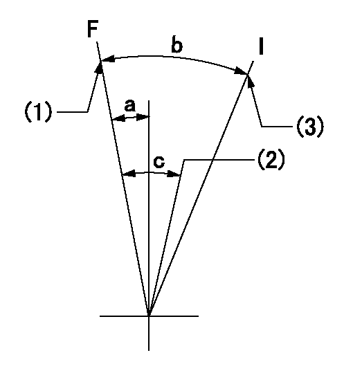
F:Full speed
I:Idle
(1)Set the pump speed at aa
(2)Set the pump speed at bb.
(3)Stopper bolt setting
----------
aa=910r/min bb=755r/min
----------
a=4deg+-5deg b=26deg+-5deg c=7deg+-5deg
----------
aa=910r/min bb=755r/min
----------
a=4deg+-5deg b=26deg+-5deg c=7deg+-5deg
Stop lever angle
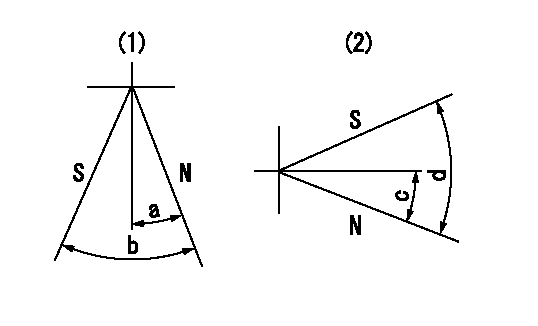
N:Pump normal
S:Stop the pump.
(1)Right front
(2)Right rear
----------
----------
a=19deg+-5deg b=46deg+-5deg c=28deg+-5deg d=53deg+-5deg
----------
----------
a=19deg+-5deg b=46deg+-5deg c=28deg+-5deg d=53deg+-5deg
0000001101
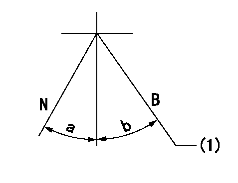
N:Normal
B:When boosted
(1)Rack position = aa (point D) at boost pressure 0.
----------
aa=12+-0.1mm
----------
a=(10deg) b=(13deg)
----------
aa=12+-0.1mm
----------
a=(10deg) b=(13deg)
Timing setting

(1)Pump vertical direction
(2)Coupling's key groove position at No 1 cylinder's beginning of injection
(3)-
(4)-
----------
----------
a=(40deg)
----------
----------
a=(40deg)
Information:
Start By:a. remove timing gear coverb. remove flywheel housingc. remove pistons and connecting rod assembliesd. remove crankshaft rear seal and wear sleevee. remove crankshaft front seal and wear sleeve Check the bearing caps for a number as to their location. If a number can be seen, put a number on the left side of the cylinder block and bearing cap. 1. Remove bolts (1) that hold main bearing caps (2) to the block, and remove main bearing caps (2). 2. Install one of the bolts from the front pulley in each end of the crankshaft.3. Fasten a hoist to the crankshaft (3), and remove crankshaft (3) from the block. The weight is 159 kg (350 lb.). If new main bearings are not to be installed, keep old bearings with identification as to their location in cylinder block. 4. Use tooling (A) to remove the crankshaft gear.5. Use tooling (B) if necessary to remove the dowel and the pin.Install Crankshaft
If the crankshaft journals and bores for the block and rods were measured at disassembly and found to be within specifications, no further checks are necessary. However, if the serviceman still wants to measure the bearing clearances, Plastigage is recommended. Lead wire, shim stock or use of a dial bore gauge can damage the bearing surface.
The servicemen must be very careful to use Plastigage, tool (B) correctly. The following points must be remembered:...Make sure that the backs of the bearings and the bores are clean and dry....Make sure that the bearing locking tabs are properly seated in their slots....The crankshaft must be free of oil where the Plastigage touches it....If the main bearing clearances are checked with the engine upright or on its side, the crankshaft must be supported. Use a jack under an adjacent crankshaft counterweight and hold the crankshaft against the crown of the bearing. If the crankshaft is not supported, the weight of the crankshaft will cause incorrect readings....Put a piece of Plastigage on the crown of the bearing half that is in the cap. Do not allow the Plastigage to extend over the edge of the bearing....Install the bearing cap using the correct torque-turn specifications. Do not use an impact wrench. Be careful not to dislodge the bearing when the cap is installed....Do not turn the crankshaft with the Plastigage installed....Carefully remove the cap but do not remove the Plastigage. Measure the width of the Plastigage while it is in the bearing cap or on the crankshaft journal. Do this by using the correct scale on the package. Record the measurements....Remove the Plastigage before reinstalling the cap.When using Plastigage, the readings can sometimes be unclear. For example, all parts of the Plastigage are not the same width. Measure the major widths to make sure that they are within the specification range. Also, experience has shown that when checking clearances tighter than 0.10 mm (.004") the readings may be low by 0.013 to 0.025 mm (.0005 to .0010"). Out-of-round journals can give faulty readings. Also, journal taper