Information injection-pump assembly
ZEXEL
106873-7770
1068737770
Rating:
Cross reference number
ZEXEL
106873-7770
1068737770
Zexel num
Bosch num
Firm num
Name
106873-7770
INJECTION-PUMP ASSEMBLY
Calibration Data:
Adjustment conditions
Test oil
1404 Test oil ISO4113 or {SAEJ967d}
1404 Test oil ISO4113 or {SAEJ967d}
Test oil temperature
degC
40
40
45
Nozzle and nozzle holder
105780-8250
Bosch type code
1 688 901 101
Nozzle
105780-0120
Bosch type code
1 688 901 990
Nozzle holder
105780-2190
Opening pressure
MPa
20.7
Opening pressure
kgf/cm2
211
Injection pipe
Outer diameter - inner diameter - length (mm) mm 8-3-600
Outer diameter - inner diameter - length (mm) mm 8-3-600
Overflow valve
131425-0220
Overflow valve opening pressure
kPa
157
123
191
Overflow valve opening pressure
kgf/cm2
1.6
1.25
1.95
Tester oil delivery pressure
kPa
255
255
255
Tester oil delivery pressure
kgf/cm2
2.6
2.6
2.6
Direction of rotation (viewed from drive side)
Right R
Right R
Injection timing adjustment
Direction of rotation (viewed from drive side)
Right R
Right R
Injection order
1-2-7-3-
4-5-6-8
Pre-stroke
mm
3.9
3.85
3.95
Beginning of injection position
Governor side NO.1
Governor side NO.1
Difference between angles 1
Cyl.1-2 deg. 45 44.5 45.5
Cyl.1-2 deg. 45 44.5 45.5
Difference between angles 2
Cal 1-7 deg. 90 89.5 90.5
Cal 1-7 deg. 90 89.5 90.5
Difference between angles 3
Cal 1-3 deg. 135 134.5 135.5
Cal 1-3 deg. 135 134.5 135.5
Difference between angles 4
Cal 1-4 deg. 180 179.5 180.5
Cal 1-4 deg. 180 179.5 180.5
Difference between angles 5
Cal 1-5 deg. 225 224.5 225.5
Cal 1-5 deg. 225 224.5 225.5
Difference between angles 6
Cal 1-6 deg. 270 269.5 270.5
Cal 1-6 deg. 270 269.5 270.5
Difference between angles 7
Cal 1-8 deg. 315 314.5 315.5
Cal 1-8 deg. 315 314.5 315.5
Injection quantity adjustment
Adjusting point
-
Rack position
12.7
Pump speed
r/min
700
700
700
Each cylinder's injection qty
mm3/st.
144
139.7
148.3
Basic
*
Fixing the rack
*
Standard for adjustment of the maximum variation between cylinders
*
Injection quantity adjustment_02
Adjusting point
Z
Rack position
8+-0.5
Pump speed
r/min
445
445
445
Each cylinder's injection qty
mm3/st.
16.5
14
19
Fixing the rack
*
Standard for adjustment of the maximum variation between cylinders
*
Injection quantity adjustment_03
Adjusting point
A
Rack position
R1(12.7)
Pump speed
r/min
700
700
700
Average injection quantity
mm3/st.
144
143
145
Basic
*
Fixing the lever
*
Injection quantity adjustment_04
Adjusting point
B
Rack position
R1+0.8
Pump speed
r/min
1100
1100
1100
Average injection quantity
mm3/st.
139
135
143
Fixing the lever
*
Injection quantity adjustment_05
Adjusting point
C
Rack position
(R1-0.8)
Pump speed
r/min
500
500
500
Average injection quantity
mm3/st.
139.5
135.5
143.5
Fixing the lever
*
Test data Ex:
Governor adjustment
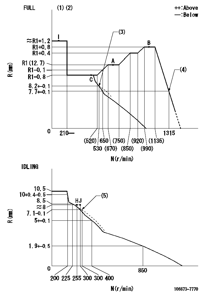
N:Pump speed
R:Rack position (mm)
(1)Torque cam stamping: T1
(2)Tolerance for racks not indicated: +-0.05mm.
(3)Air cylinder ON
(4)Air cylinder OFF
(5)Damper spring setting
----------
T1=AD95
----------
----------
T1=AD95
----------
Timer adjustment

(1)Adjusting range
(2)Step response time
(N): Speed of the pump
(L): Load
(theta) Advance angle
(Srd1) Step response time 1
(Srd2) Step response time 2
1. Adjusting conditions for the variable timer
(1)Adjust the clearance between the pickup and the protrusion to L.
----------
L=1-0.2mm N2=800r/min C2=(10)deg t1=2.5--sec. t2=2.5--sec.
----------
N1=750++r/min P1=0kPa(0kgf/cm2) P2=392kPa(4kgf/cm2) C1=10+-0.3deg R01=0/4load R02=4/4load
----------
L=1-0.2mm N2=800r/min C2=(10)deg t1=2.5--sec. t2=2.5--sec.
----------
N1=750++r/min P1=0kPa(0kgf/cm2) P2=392kPa(4kgf/cm2) C1=10+-0.3deg R01=0/4load R02=4/4load
Speed control lever angle
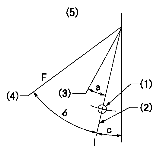
F:Full speed
I:Idle
(1)Use the hole at R = aa
(2)Stopper bolt set position 'H'
(3)When air cylinder ON.
(4)When air cylinder OFF.
(5)Viewed from feed pump side.
----------
aa=37.5mm
----------
a=(16deg) b=34deg+-3deg c=30deg+-5deg
----------
aa=37.5mm
----------
a=(16deg) b=34deg+-3deg c=30deg+-5deg
Stop lever angle
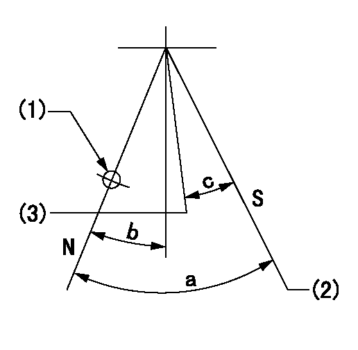
N:Pump normal
S:Stop the pump.
(1)Use the hole at R = aa
(2)Set the stopper bolt so that speed = bb and rack position = cc. (Confirm non-injection.)
(3)Normal engine position (Rack position corresponding to dd)
----------
aa=54mm bb=1100r/min cc=3.5+-0.3mm dd=18mm
----------
a=41deg+-5deg b=5.5deg+-5deg c=(31deg)
----------
aa=54mm bb=1100r/min cc=3.5+-0.3mm dd=18mm
----------
a=41deg+-5deg b=5.5deg+-5deg c=(31deg)
0000001501 RACK SENSOR

(VR) measurement voltage
(I) Part number of the control unit
(G) Apply red paint.
(H): End surface of the pump
1. Rack sensor adjustment (-0620)
(1)Fix the speed control lever at the full position
(2)Set the speed to N1 r/min.
(If the boost compensator is provided, apply boost pressure.)
(3)Adjust the bobbin (A) so that the rack sensor's output voltage is VR+-0.01.
(4)At that time, rack position must be Ra.
(5)Apply G at two places.
Connecting part between the joint (B) and the nut (F)
Connecting part between the joint (B) and the end surface of the pump (H)
----------
N1=1100r/min Ra=R1(12.7)+0.8mm
----------
----------
N1=1100r/min Ra=R1(12.7)+0.8mm
----------
0000001601 AIR CYLINDER
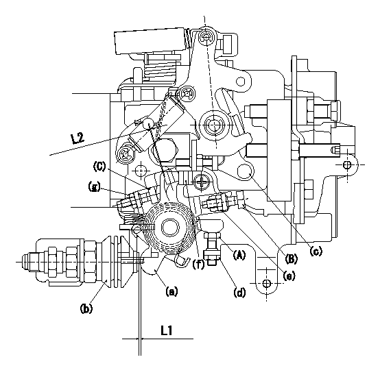
<A> stopper bolt
<B> stopper bolt
<C> stopper bolt
(a) lever
(b) air cylinder
(c) speed lever
(d) Nut
(e) nut
(f) lever
(g) nut
1. Stopper bolt <A> adjustment method
(1)When air cylinder pressure is P1, set the gap between the lever (a) and the air cylinder (b) to L1.
(2)Confirm that the speed lever (c) operates between idling and full speed.
(3)Fix stopper bolt <A> using nut (d).
2. Stopper bolt <B> adjustment method.
(1)At air cylinder pressure P2, pump speed N1 and rack position is R1, adjust stopper bolt (B) so that the speed lever (c) is in the stop position.
(2)Turn the stopper bolt (c) so that the clearance between lever (a) and lever (f) is L2, then fix using nut (g).
(3)Move the lever (a) several times and fix stopper bolt <B> using the nut (e).
(4)Tightening torque T1 for nuts (d), (e) and (g)
----------
L1=0.2++mm L2=0~1.5++mm P1=0kPa(0kgf/cm2) P2=686+98kpa(7+1kgf/cm2) N1=530r/min R1=8.2+-0.1mm T1=4.9~6.86N-m(0.5~0.7kgf-m)
----------
----------
L1=0.2++mm L2=0~1.5++mm P1=0kPa(0kgf/cm2) P2=686+98kpa(7+1kgf/cm2) N1=530r/min R1=8.2+-0.1mm T1=4.9~6.86N-m(0.5~0.7kgf-m)
----------
Timing setting

(1)Pump vertical direction
(2)Coupling's key groove position at No 1 cylinder's beginning of injection
(3)B.T.D.C.: aa
(4)-
----------
aa=6deg
----------
a=(50deg)
----------
aa=6deg
----------
a=(50deg)
Information:
6V7070 Heavy-Duty Digital MultimeterThe 6V7070 Heavy-Duty Digital Multimeter is a completely portable, hand held instrument with a digital display. This multimeter is built with extra protection against damage in field applications, and is equipped with seven functions and 29 ranges. The 6V7070 Multimeter has an instant ohms indicator that permits continuity checks for fast circuit inspection. It also can be used for troubleshooting small value capacitors.The 6V7800 Regular-Duty Digital Multimeter (a low cost option to the Heavy-Duty Multimeter) is also available; however, the 6V7800 Multimeter does not have the 10A range or the instant ohms feature of the 6V7070 Multimeter. Make reference to Special Instruction, Form No. SEHS7734 for more complete information for use of the 6V7070 and 6V7800 MultimetersBattery
Never disconnect any charging unit circuit or battery circuit cable from battery when the charging unit is operated. A spark can cause an explosion from the flammable vapor mixture of hydrogen and oxygen that is released from the electrolyte through the battery outlets. Injury to personnel can be the result.
The battery circuit is an electrical load on the charging unit. The load is variable because of the condition of the charge in the battery. Damage to the charging unit can result if the connections (either positive or negative) between the battery and charging unit are broken while the charging unit is in operation. This is because the battery load is lost and there is an increase in charging voltage. High voltage can damage, not only the charging unit, but also the regulator and other electrical components.Use the 6V4930 Battery Load Tester, the 8T0900 Clamp-On Ammeter and the 6V7070 Multimeter to load test a battery that does not hold a charge when in use. See Special Instruction, Form No. SEHS8268 for the correct procedure and specifications to use.Charging System
The condition of charge in the battery at each regular inspection will show if the charging system operates correctly. An adjustment is necessary when the battery is constantly in a low condition of charge or a large amount of water is needed (more than one ounce of water per cell per week or per every 100 service hours).When it is possible, make a test of the charging unit and voltage regulator on the engine, and use wiring and components that are a permanent part of the system. Off-engine (bench) testing will give a test of the charging unit and voltage regulator operation. This testing will give an indication of needed repair. After repairs are made, again make a test to give proof that the units are repaired to their original condition of operation.Before the start of on-engine testing, the charging system and battery must be checked as shown in the Steps that follow:1. Battery must be at least 75% (1.225 Sp.Gr.) fully charged and held tightly in place. The Battery holder must not put too much stress on the battery.2. Cables between the battery, starter and engine ground must be the correct size. Wires and cables must be free of corrosion and
Have questions with 106873-7770?
Group cross 106873-7770 ZEXEL
Mitsubishi
Mitsubishi
Mitsubishi
Mitsubishi
Mitsubishi
Mitsubishi
106873-7770
INJECTION-PUMP ASSEMBLY