Information injection-pump assembly
ZEXEL
106873-7670
1068737670
Rating:
Cross reference number
ZEXEL
106873-7670
1068737670
Zexel num
Bosch num
Firm num
Name
106873-7670
INJECTION-PUMP ASSEMBLY
Calibration Data:
Adjustment conditions
Test oil
1404 Test oil ISO4113 or {SAEJ967d}
1404 Test oil ISO4113 or {SAEJ967d}
Test oil temperature
degC
40
40
45
Nozzle and nozzle holder
105780-8250
Bosch type code
1 688 901 101
Nozzle
105780-0120
Bosch type code
1 688 901 990
Nozzle holder
105780-2190
Opening pressure
MPa
20.7
Opening pressure
kgf/cm2
211
Injection pipe
Outer diameter - inner diameter - length (mm) mm 8-3-600
Outer diameter - inner diameter - length (mm) mm 8-3-600
Overflow valve
131425-0220
Overflow valve opening pressure
kPa
157
123
191
Overflow valve opening pressure
kgf/cm2
1.6
1.25
1.95
Tester oil delivery pressure
kPa
255
255
255
Tester oil delivery pressure
kgf/cm2
2.6
2.6
2.6
RED3 control unit part number
407910-2
470
RED3 rack sensor specifications
mm
15
Direction of rotation (viewed from drive side)
Right R
Right R
Injection timing adjustment
Direction of rotation (viewed from drive side)
Right R
Right R
Injection order
1-2-7-3-
4-5-6-8
Pre-stroke
mm
3.9
3.85
3.95
Beginning of injection position
Governor side NO.1
Governor side NO.1
Difference between angles 1
Cyl.1-2 deg. 45 44.5 45.5
Cyl.1-2 deg. 45 44.5 45.5
Difference between angles 2
Cal 1-7 deg. 90 89.5 90.5
Cal 1-7 deg. 90 89.5 90.5
Difference between angles 3
Cal 1-3 deg. 135 134.5 135.5
Cal 1-3 deg. 135 134.5 135.5
Difference between angles 4
Cal 1-4 deg. 180 179.5 180.5
Cal 1-4 deg. 180 179.5 180.5
Difference between angles 5
Cal 1-5 deg. 225 224.5 225.5
Cal 1-5 deg. 225 224.5 225.5
Difference between angles 6
Cal 1-6 deg. 270 269.5 270.5
Cal 1-6 deg. 270 269.5 270.5
Difference between angles 7
Cal 1-8 deg. 315 314.5 315.5
Cal 1-8 deg. 315 314.5 315.5
Injection quantity adjustment
Rack position
(10.7)
Vist
V
1.86
1.86
1.86
Pump speed
r/min
700
700
700
Average injection quantity
mm3/st.
125
124
126
Max. variation between cylinders
%
0
-3
3
Basic
*
Injection quantity adjustment_02
Rack position
(6.5)
Vist
V
2.7
2.6
2.8
Pump speed
r/min
380
380
380
Average injection quantity
mm3/st.
16
14
18
Max. variation between cylinders
%
0
-15
15
Test data Ex:
Governor adjustment

(1)Adjusting range
(2)Step response time
(N): Speed of the pump
(L): Load
(theta) Advance angle
(Srd1) Step response time 1
(Srd2) Step response time 2
1. Adjusting conditions for the variable timer
(1)Adjust the clearance between the pickup and the protrusion to L.
----------
L=1-0.2mm N2=800r/min C2=(10)deg t1=2.5--sec. t2=2.5--sec.
----------
N1=750++r/min P1=0kPa(0kgf/cm2) P2=392kPa(4kgf/cm2) C1=10+-0.3deg R01=0/4load R02=4/4load
----------
L=1-0.2mm N2=800r/min C2=(10)deg t1=2.5--sec. t2=2.5--sec.
----------
N1=750++r/min P1=0kPa(0kgf/cm2) P2=392kPa(4kgf/cm2) C1=10+-0.3deg R01=0/4load R02=4/4load
Speed control lever angle
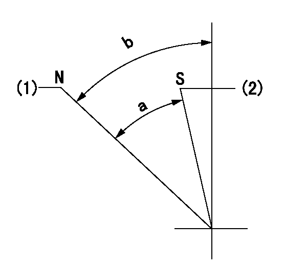
N:Pump normal
S:Stop the pump.
(1)Rack position = aa
(2)Rack position bb
----------
aa=16mm bb=1mm
----------
a=29deg+-5deg b=45deg+-5deg
----------
aa=16mm bb=1mm
----------
a=29deg+-5deg b=45deg+-5deg
0000000901

(1)Pump vertical direction
(2)Coupling's key groove position at No 1 cylinder's beginning of injection
(3)B.T.D.C.: aa
(4)-
----------
aa=4deg
----------
a=(50deg)
----------
aa=4deg
----------
a=(50deg)
Stop lever angle

(Rs) rack sensor specifications
(C/U) control unit part number
(V) Rack sensor output voltage
(R) Rack position (mm)
1. Confirming governor output characteristics (rack 15 mm, span 6 mm)
(1)When the output voltages of the rack sensor are V1 and V2, check that the rack positions R1 and R2 in the table above are satisfied.
----------
----------
----------
----------
0000001201 RACK SENSOR

(VR) measurement voltage
(I) Part number of the control unit
(G) Apply red paint.
(H): End surface of the pump
1. Rack sensor adjustment (154610-0620)
(1)At governor side rack sensor output voltage V1, adjust the bobbin (A) so that the drive side rack sensor output voltage is VR+-0.01.
(2)Apply G at two places.
Connecting part between the joint (B) and the nut (F)
Connecting part between the joint (B) and the end surface of the pump (H)
----------
V1=1V
----------
----------
V1=1V
----------
Information:
Use of the Pickup During Wet Conditions
If the pickup becomes wet, it may operate intermittently or not at all. Although the pickup is water resistant, it is not waterproof. Water spray from rain or other sources may cause the pickup to stop producing an output signal.If this happens, the pickup should be removed from the engine and allowed to dry out thoroughly. If necessary, the pickup can be dried in an oven at approximately 50°C (122°F). After drying, the pickup should operate correctly.If it is not possible to keep the pickup dry, use the following procedure: If the pickup must be used during wet conditions, it may be possible to protect it from moisture by using a water displacing spray such as WD-40®.Remove the pickup from the engine. Thoroughly spray the pickup from all directions. Make sure the pickup is completely covered with the spray. Reinstall the pickup on the engine and check its operation.When water first contacts the pickup, the unit may stop working temporarily, but will start working again after the water has been displaced by the solution. If necessary, spray the solution on the pickup after installation on the injection line.Permanent Installation on the Engine
If the pickup is to be permanently installed on the engine, install the pickup on the fuel injection line in the usual manner. Make sure that the thumbscrew is hand tightened securely, but not over tightened. Run the engine and check the operation of the pickup.Make sure that the pickup and line are clean and dry. If the pickup is working correctly, use a can of spray paint to thoroughly paint the pickup from all directions. Several coats should be applied. Let the paint dry thoroughly before operating the engine.Checking the Operation of the Amplifier and Pickup
(1) 6V2100 Multitach. (2) 5P9698 Calibrator. (3) 5P7366 Power Cable. (4) Digital Multimeter. (5) Screwdriver. (6) 6V6152 Adapter. Screwdriver (5) should have a blade approximately 150 mm (6 in) long with 6 mm (.25 in) diameter shaft of round bare metal (not anodized or insulated).The 6V6152 Adapter (6) is a phono plug-to-BNC connector. Modifications must be made to the 5P9698 Calibrator (2). Refer to Special Instruction, SMHS7504-01.Checking the 4C6812 Amplifier
(1) 6V6152 Adapter Plug. (2) 5P9698 Calibrator. (3) 4C6812 Amplifier. (4) Connector. (5) 5P7366 Power Cable. (6) Knob. (7) Battery Indicator. (8) No Input Signal Light.1. Install 6V6152 Adapter Plug (1) on the end of the output cable on 5P9698 Calibrator (2). Plug the adapter into 4C6812 Amplifier (3).2. Check the operation of the multitach being used by performing the CHECKING PHOTO OPERATION test procedure contained in Special Instruction SEHS7807. (This is to ensure it is operating correctly on PHOTO operation.)3. Plug connector (4), on the end of the amplifier output cable, into the PH (photo) connector on the multitach. Attach 5P7366 Power Cable (5) to the multitach and to a suitable power source. Refer to SEHS7807.4. Program the multitach for .5 P/REV and to read R/MIN on the PH (photo) input. Turn knob (6) on
Have questions with 106873-7670?
Group cross 106873-7670 ZEXEL
Mitsubishi
Mitsubishi
Mitsubishi
Mitsubishi
Mitsubishi
106873-7670
INJECTION-PUMP ASSEMBLY