Information injection-pump assembly
ZEXEL
106873-7660
1068737660
Rating:
Cross reference number
ZEXEL
106873-7660
1068737660
Zexel num
Bosch num
Firm num
Name
106873-7660
INJECTION-PUMP ASSEMBLY
Calibration Data:
Adjustment conditions
Test oil
1404 Test oil ISO4113 or {SAEJ967d}
1404 Test oil ISO4113 or {SAEJ967d}
Test oil temperature
degC
40
40
45
Nozzle and nozzle holder
105780-8140
Bosch type code
EF8511/9A
Nozzle
105780-0000
Bosch type code
DN12SD12T
Nozzle holder
105780-2080
Bosch type code
EF8511/9
Opening pressure
MPa
17.2
Opening pressure
kgf/cm2
175
Injection pipe
Outer diameter - inner diameter - length (mm) mm 8-3-600
Outer diameter - inner diameter - length (mm) mm 8-3-600
Overflow valve
131424-4620
Overflow valve opening pressure
kPa
255
221
289
Overflow valve opening pressure
kgf/cm2
2.6
2.25
2.95
Tester oil delivery pressure
kPa
157
157
157
Tester oil delivery pressure
kgf/cm2
1.6
1.6
1.6
Direction of rotation (viewed from drive side)
Right R
Right R
Injection timing adjustment
Direction of rotation (viewed from drive side)
Right R
Right R
Injection order
1-2-7-3-
4-5-6-8
Pre-stroke
mm
4.8
4.75
4.85
Beginning of injection position
Governor side NO.1
Governor side NO.1
Difference between angles 1
Cyl.1-2 deg. 45 44.5 45.5
Cyl.1-2 deg. 45 44.5 45.5
Difference between angles 2
Cal 1-7 deg. 90 89.5 90.5
Cal 1-7 deg. 90 89.5 90.5
Difference between angles 3
Cal 1-3 deg. 135 134.5 135.5
Cal 1-3 deg. 135 134.5 135.5
Difference between angles 4
Cal 1-4 deg. 180 179.5 180.5
Cal 1-4 deg. 180 179.5 180.5
Difference between angles 5
Cal 1-5 deg. 225 224.5 225.5
Cal 1-5 deg. 225 224.5 225.5
Difference between angles 6
Cal 1-6 deg. 270 269.5 270.5
Cal 1-6 deg. 270 269.5 270.5
Difference between angles 7
Cal 1-8 deg. 315 314.5 315.5
Cal 1-8 deg. 315 314.5 315.5
Injection quantity adjustment
Adjusting point
A
Rack position
10.9
Pump speed
r/min
800
800
800
Average injection quantity
mm3/st.
151.8
148.8
154.8
Max. variation between cylinders
%
0
-3
3
Basic
*
Fixing the lever
*
Boost pressure
kPa
61.3
61.3
Boost pressure
mmHg
460
460
Injection quantity adjustment_02
Adjusting point
B
Rack position
5.6+-0.5
Pump speed
r/min
275
275
275
Average injection quantity
mm3/st.
15.5
12.9
18.1
Max. variation between cylinders
%
0
-15
15
Fixing the rack
*
Boost pressure
kPa
0
0
0
Boost pressure
mmHg
0
0
0
Boost compensator adjustment
Pump speed
r/min
500
500
500
Rack position
10.2
Boost pressure
kPa
21.3
21.3
21.3
Boost pressure
mmHg
160
160
160
Boost compensator adjustment_02
Pump speed
r/min
500
500
500
Rack position
10.5
Boost pressure
kPa
41.3
40
42.6
Boost pressure
mmHg
310
300
320
Boost compensator adjustment_03
Pump speed
r/min
500
500
500
Rack position
10.9
Boost pressure
kPa
48
48
48
Boost pressure
mmHg
360
360
360
Timer adjustment
Pump speed
r/min
950--
Advance angle
deg.
0
0
0
Remarks
Start
Start
Timer adjustment_02
Pump speed
r/min
900
Advance angle
deg.
0.5
Timer adjustment_03
Pump speed
r/min
1100
Advance angle
deg.
0.5
0
1
Timer adjustment_04
Pump speed
r/min
-
Advance angle
deg.
1
1
1
Remarks
Measure the actual speed, stop
Measure the actual speed, stop
Test data Ex:
Governor adjustment
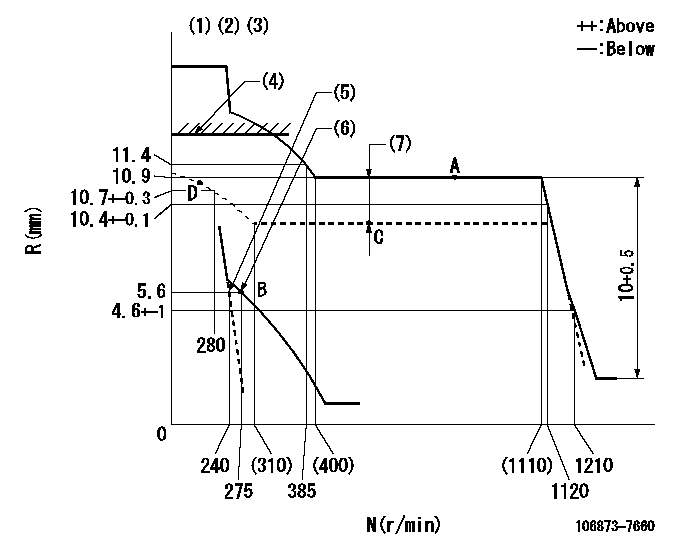
N:Pump speed
R:Rack position (mm)
(1)Variable speed specification.
(2)Tolerance for racks not indicated: +-0.05mm.
(3)Supplied with damper spring not set.
(4)Rack limit using excess fuel lever: L1
(5)Main spring setting
(6)Set idle sub-spring
(7)Boost compensator stroke: BCL
----------
L1=13.5+0.5mm BCL=0.7+-0.1mm
----------
----------
L1=13.5+0.5mm BCL=0.7+-0.1mm
----------
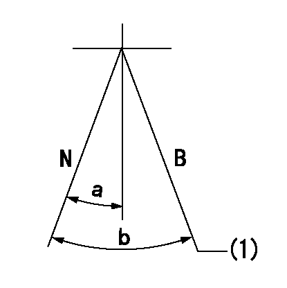
Speed control lever angle

F:Full speed
I:Idle
(1)Stopper bolt setting
----------
----------
a=(18deg)+-3deg b=(16deg)+-5deg
----------
----------
a=(18deg)+-3deg b=(16deg)+-5deg
0000000901
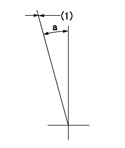
(1)Fix full load
----------
----------
a=15deg+-5deg
----------
----------
a=15deg+-5deg
Stop lever angle
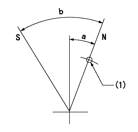
N:Pump normal
S:Stop the pump.
(1)Use the hole at R = aa
----------
aa=30mm
----------
a=33deg+-5deg b=71deg+-5deg
----------
aa=30mm
----------
a=33deg+-5deg b=71deg+-5deg
0000001101
N:Normal
B:When boosted
(1)Rack position = aa, stopper bolt setting
----------
aa=13.5+0.5mm
----------
a=(5deg) b=(20deg)
----------
aa=13.5+0.5mm
----------
a=(5deg) b=(20deg)
Timing setting

(1)Pump vertical direction
(2)Coupling's key groove position at No 1 cylinder's beginning of injection
(3)B.T.D.C.: aa
(4)-
----------
aa=18deg
----------
a=(40deg)
----------
aa=18deg
----------
a=(40deg)
Information:
Illustration 15: (A) Injector sleeve. (3) Lower pilot. (36) Pipe or tubing.6. Place new injector sleeve (A) into its bore in the cylinder head. Wipe away any excess retaining compound that is either in or above the injector sleeve.7. Install lower pilot (3) into the injector sleeve. To avoid damage to the guide on the lower pilot (3), use a piece of pipe or tubing (36) with a small hammer to LIGHTLY tap the lower pilot. This will ensure that the new injector sleeve is fully seated in the cylinder head.Remove lower pilot (3).
Illustration 16: (14) Roller expander. (32) Mandrel.8. Place a coating of clean engine oil on 4C-6730 Roller Expander (14). Ensure the rollers are completely covered with oil.9. Pull and hold mandrel (32) out of the roller expander (14) as far as possible. Then completely insert the roller expander into the injector sleeve.10. Place a torque wrench with a 11 mm socket on the hex portion of 4C-6730 Roller Expander mandrel. Turn the torque wrench in a clockwise (CW) direction in order to achieve a torque of 11 N m (100 lb in). If torque stops increasing before 11 N m (100 lb in) the sleeve is not hard enough or the bore is oversized in the head.
To ensure that accurate torque is achieved, a calibrated 4C-6936 Torque Wrench or equivalent is required.
11. When the specified torque is reached, stop turning the roller expander in the clockwise (CW) direction. Now turn the roller expander in the counterclockwise (CCW) direction until it is loose in the injector sleeve.Remove 4C-6730 Roller Expander from the injector sleeve.12. Wipe the roller expander, especially the rollers, to remove any traces of 7M-7456 Bearing Mount or Loctite® 609 that may have built up from the injector sleeve. When usage of 4C-6730 Roller Expander is completed, clean it thoroughly using either 1U-8803 Cleaner Concentrate or 8T-9011 Component Cleaner. After the cleaning, place a generous coat of either 1U-8265 Penetrating Oil or 1U-8809 Rust Preventive on the roller expander. Place it in its storage case.
Illustration 17: (A) Injector sleeve. (13) Driver. (15) Guide bushing. Wage/flaring assembly: (8) Set screw. (9) Bottom swage. (11) Flare tool.13. Install 4C-6591 Bottom Swage (9) in 9U-6856 Flare Tool (11) using 4C-5502 Set Screw (8).14. Slide same guide bushing (15) used previously onto 9U-6856 Flare Tool (11).
Some 9U-6856 Flare Tools have their part number stamped on the turn which fits into the guide bushing. This arrangement interferes with the fit. Before the first tool use, the part number should be filed down as necessary in order to permit fit of the flare tool in the guide bushing.
15. Use 5P-3931 Anti-seize Compound, 6V-4876 Molykote Paste Lubricant, or grease to lubricate the swage/flaring assembly. Place it into the sleeve with the flare tool prying notch facing either opening between the valve springs. This will allow access for removal of the swage/flaring assembly.16. Place 9U-6857 Driver (13) on 9U-6856 Flare Tool (11).17. Use a hammer to drive down the swage/flaring assembly until
Have questions with 106873-7660?
Group cross 106873-7660 ZEXEL
Mitsubishi
Mitsubishi
Mitsubishi
Mitsubishi
106873-7660
INJECTION-PUMP ASSEMBLY