Information injection-pump assembly
BOSCH
9 400 618 503
9400618503
ZEXEL
106873-7622
1068737622
MITSUBISHI
ME163224
me163224
Rating:
Cross reference number
BOSCH
9 400 618 503
9400618503
ZEXEL
106873-7622
1068737622
MITSUBISHI
ME163224
me163224
Zexel num
Bosch num
Firm num
Name
106873-7622
9 400 618 503
ME163224 MITSUBISHI
INJECTION-PUMP ASSEMBLY
8M20 K 14CD INJECTION PUMP ASSY PE8P PE
8M20 K 14CD INJECTION PUMP ASSY PE8P PE
Calibration Data:
Adjustment conditions
Test oil
1404 Test oil ISO4113 or {SAEJ967d}
1404 Test oil ISO4113 or {SAEJ967d}
Test oil temperature
degC
40
40
45
Nozzle and nozzle holder
105780-8250
Bosch type code
1 688 901 101
Nozzle
105780-0120
Bosch type code
1 688 901 990
Nozzle holder
105780-2190
Opening pressure
MPa
20.7
Opening pressure
kgf/cm2
211
Injection pipe
Outer diameter - inner diameter - length (mm) mm 8-3-600
Outer diameter - inner diameter - length (mm) mm 8-3-600
Overflow valve
131425-0220
Overflow valve opening pressure
kPa
157
123
191
Overflow valve opening pressure
kgf/cm2
1.6
1.25
1.95
Tester oil delivery pressure
kPa
255
255
255
Tester oil delivery pressure
kgf/cm2
2.6
2.6
2.6
Direction of rotation (viewed from drive side)
Right R
Right R
Injection timing adjustment
Direction of rotation (viewed from drive side)
Right R
Right R
Injection order
1-2-7-3-
4-5-6-8
Pre-stroke
mm
3.9
3.85
3.95
Beginning of injection position
Governor side NO.1
Governor side NO.1
Difference between angles 1
Cyl.1-2 deg. 45 44.5 45.5
Cyl.1-2 deg. 45 44.5 45.5
Difference between angles 2
Cal 1-7 deg. 90 89.5 90.5
Cal 1-7 deg. 90 89.5 90.5
Difference between angles 3
Cal 1-3 deg. 135 134.5 135.5
Cal 1-3 deg. 135 134.5 135.5
Difference between angles 4
Cal 1-4 deg. 180 179.5 180.5
Cal 1-4 deg. 180 179.5 180.5
Difference between angles 5
Cal 1-5 deg. 225 224.5 225.5
Cal 1-5 deg. 225 224.5 225.5
Difference between angles 6
Cal 1-6 deg. 270 269.5 270.5
Cal 1-6 deg. 270 269.5 270.5
Difference between angles 7
Cal 1-8 deg. 315 314.5 315.5
Cal 1-8 deg. 315 314.5 315.5
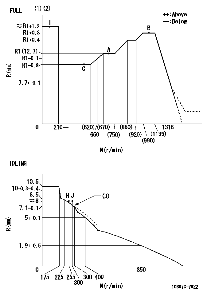
Injection quantity adjustment
Adjusting point
-
Rack position
12.7
Pump speed
r/min
700
700
700
Each cylinder's injection qty
mm3/st.
144
139.7
148.3
Basic
*
Fixing the rack
*
Injection quantity adjustment_02
Adjusting point
Z
Rack position
8+-0.5
Pump speed
r/min
445
445
445
Each cylinder's injection qty
mm3/st.
16.5
14
19
Fixing the rack
*
Injection quantity adjustment_03
Adjusting point
A
Rack position
R1(12.7)
Pump speed
r/min
700
700
700
Average injection quantity
mm3/st.
144
143
145
Basic
*
Fixing the lever
*
Injection quantity adjustment_04
Adjusting point
B
Rack position
R1+0.8
Pump speed
r/min
1100
1100
1100
Average injection quantity
mm3/st.
139
135
143
Fixing the lever
*
Injection quantity adjustment_05
Adjusting point
C
Rack position
(R1-0.8)
Pump speed
r/min
500
500
500
Average injection quantity
mm3/st.
139.5
135.5
143.5
Fixing the lever
*
Test data Ex:
Governor adjustment
N:Pump speed
R:Rack position (mm)
(1)Torque cam stamping: T1
(2)Tolerance for racks not indicated: +-0.05mm.
(3)Damper spring setting
----------
T1=AD95
----------
----------
T1=AD95
----------
Timer adjustment

(1)Adjusting range
(2)Step response time
(N): Speed of the pump
(L): Load
(theta) Advance angle
(Srd1) Step response time 1
(Srd2) Step response time 2
1. Adjusting conditions for the variable timer
(1)Adjust the clearance between the pickup and the protrusion to L.
----------
L=1-0.2mm N2=800r/min C2=(10)deg t1=2.5--sec. t2=2.5--sec.
----------
N1=750++r/min P1=0kPa(0kgf/cm2) P2=392kPa(4kgf/cm2) C1=10+-0.3deg R01=0/4load R02=4/4load
----------
L=1-0.2mm N2=800r/min C2=(10)deg t1=2.5--sec. t2=2.5--sec.
----------
N1=750++r/min P1=0kPa(0kgf/cm2) P2=392kPa(4kgf/cm2) C1=10+-0.3deg R01=0/4load R02=4/4load
Speed control lever angle
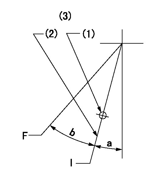
F:Full speed
I:Idle
(1)Use the hole at R = aa
(2)Stopper bolt setting
(3)Viewed from feed pump side.
----------
aa=37.5mm
----------
a=30deg+-5deg b=34deg+-3deg
----------
aa=37.5mm
----------
a=30deg+-5deg b=34deg+-3deg
Stop lever angle
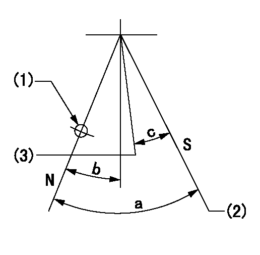
N:Pump normal
S:Stop the pump.
(1)Use the hole at R = aa
(2)Set the stopper bolt so that speed = bb and rack position = cc. (Confirm non-injection.)
(3)Normal engine position (equivalent to R = dd).
----------
aa=54mm bb=1100r/min cc=3.5+-0.3mm dd=18mm
----------
a=41deg+-5deg b=5.5deg+-5deg c=(31deg)
----------
aa=54mm bb=1100r/min cc=3.5+-0.3mm dd=18mm
----------
a=41deg+-5deg b=5.5deg+-5deg c=(31deg)
0000001501 RACK SENSOR

(VR) measurement voltage
(I) Part number of the control unit
(G) Apply red paint.
(H): End surface of the pump
1. Rack sensor adjustment (-0620)
(1)Fix the speed control lever at the full position
(2)Set the speed to N1 r/min.
(If the boost compensator is provided, apply boost pressure.)
(3)Adjust the bobbin (A) so that the rack sensor's output voltage is VR+-0.01.
(4)At that time, rack position must be Ra.
(5)Apply G at two places.
Connecting part between the joint (B) and the nut (F)
Connecting part between the joint (B) and the end surface of the pump (H)
----------
N1=1100r/min Ra=R1(12.7)+0.8mm
----------
----------
N1=1100r/min Ra=R1(12.7)+0.8mm
----------
Timing setting

(1)Pump vertical direction
(2)Coupling's key groove position at No 1 cylinder's beginning of injection
(3)B.T.D.C.: aa
(4)-
----------
aa=6deg
----------
a=(50deg)
----------
aa=6deg
----------
a=(50deg)
Information:
(3) Remove all dirt, rust and foreign material from the surfaces on transmission input flange (3), shaft assembly (4) and spacer group (2). Use a file to remove all burrs or damaged areas on the surfaces. Install shaft assembly (4) on flange (3) with bolts (5) and the nuts. Push the crankshaft to the front of its travel with a pry bar. Loosely install spacer (2). Put a feeler gauge equal to one-half the crankshaft end play (see step 2, page 6 for the dimension) between spacer (2) and coupling (1) at (S). Move the engine to the front or rear as needed to get clearance equal to the feeler gauge thickness. Remove spacer (2). Install 6V2042 Alignment Yoke (6) and 6V2043 Alignment Bar (7) on shaft (4) with two 13.0 mm Ø (.5"Ø) threaded rods and nuts. Install two dial indicators (8) and (9) as shown, one on surface (Y) and one on surface (Z). Use a pry bar to push the crankshaft to the front of its travel. Set the indicators to "0" in this position. (4) Indicator (8), on surface (Y), will show face alignment. Slowly turn shaft (4) by hand; do not use yoke (6) to turn the shaft. Make a record of the indicator readings 90° apart at (A), (B), (C) and (D). Face alignment as shown by the indicator must be as follows: a) A maximum TIR between (A) and (C) of 0.25 mm (.010") is permitted. The reading at (C) must be plus (+). This dimension is needed, because as an application of engine torque is made to the propeller shaft, the transmission will tip forward a small amount and both dimensions will be the same.b) A maximum TIR between (B) and (D) of 0.25 mm (0.010") is permitted but the reading at (B) plus the reading at (D) must be equal to the reading at (C). (5) Indicator (9) on surface (Z) will show bore alignment. Put the indicator on "0" at location (A). Slowly turn shaft (4) and make a record of the indicator readings 90° apart at (A), (B), (C) and (D). Bore alignment as shown by indicator (9) must be as follows: a) The TIR between (A) and (C) must be 0.64 0.25 mm (.025" .010"). IMPORTANT: Because the centerline of the crankshaft must be below the centerline of the coupling shaft, the indicator reading at (C) must be plus (+) when the reading at (A) is 0.00 mm (.000") and indicator (9) is installed as shown.b) The TIR between (B) and (D) can be a maximum of 0.13 (.005"). The reading at (B) plus (D) must equal the reading at (C).(6) Move the engine as necessary to get the alignment dimensions given. (7) Loosely connect shaft (4) to coupling (1) with two bolts (18). Do not install the spacer between the shaft and the coupling at this time. Rotate the engine and transmission input shaft together and take the dial indicator readings
Have questions with 106873-7622?
Group cross 106873-7622 ZEXEL
Mitsubishi
Mitsubishi
106873-7622
9 400 618 503
ME163224
INJECTION-PUMP ASSEMBLY
8M20
8M20