Information injection-pump assembly
BOSCH
9 400 611 043
9400611043
ZEXEL
106873-7480
1068737480
MITSUBISHI
ME094508
me094508

Rating:
Service parts 106873-7480 INJECTION-PUMP ASSEMBLY:
1.
_
7.
COUPLING PLATE
8.
_
9.
_
11.
Nozzle and Holder
ME093733
12.
Open Pre:MPa(Kqf/cm2)
15.7{160}/21.6{220}
14.
NOZZLE
Include in #1:
106873-7480
as INJECTION-PUMP ASSEMBLY
Cross reference number
BOSCH
9 400 611 043
9400611043
ZEXEL
106873-7480
1068737480
MITSUBISHI
ME094508
me094508
Zexel num
Bosch num
Firm num
Name
106873-7480
9 400 611 043
ME094508 MITSUBISHI
INJECTION-PUMP ASSEMBLY
8DC9 K
8DC9 K
Calibration Data:
Adjustment conditions
Test oil
1404 Test oil ISO4113 or {SAEJ967d}
1404 Test oil ISO4113 or {SAEJ967d}
Test oil temperature
degC
40
40
45
Nozzle and nozzle holder
105780-8250
Bosch type code
1 688 901 101
Nozzle
105780-0120
Bosch type code
1 688 901 990
Nozzle holder
105780-2190
Opening pressure
MPa
20.7
Opening pressure
kgf/cm2
211
Injection pipe
Outer diameter - inner diameter - length (mm) mm 8-3-600
Outer diameter - inner diameter - length (mm) mm 8-3-600
Overflow valve
131425-0220
Overflow valve opening pressure
kPa
157
123
191
Overflow valve opening pressure
kgf/cm2
1.6
1.25
1.95
Tester oil delivery pressure
kPa
255
255
255
Tester oil delivery pressure
kgf/cm2
2.6
2.6
2.6
RED3 control unit part number
407910-2
470
RED3 rack sensor specifications
mm
15
Direction of rotation (viewed from drive side)
Right R
Right R
Injection timing adjustment
Direction of rotation (viewed from drive side)
Right R
Right R
Injection order
1-2-7-3-
4-5-6-8
Pre-stroke
mm
3.9
3.85
3.95
Beginning of injection position
Governor side NO.1
Governor side NO.1
Difference between angles 1
Cyl.1-2 deg. 45 44.5 45.5
Cyl.1-2 deg. 45 44.5 45.5
Difference between angles 2
Cal 1-7 deg. 90 89.5 90.5
Cal 1-7 deg. 90 89.5 90.5
Difference between angles 3
Cal 1-3 deg. 135 134.5 135.5
Cal 1-3 deg. 135 134.5 135.5
Difference between angles 4
Cal 1-4 deg. 180 179.5 180.5
Cal 1-4 deg. 180 179.5 180.5
Difference between angles 5
Cal 1-5 deg. 225 224.5 225.5
Cal 1-5 deg. 225 224.5 225.5
Difference between angles 6
Cal 1-6 deg. 270 269.5 270.5
Cal 1-6 deg. 270 269.5 270.5
Difference between angles 7
Cal 1-8 deg. 315 314.5 315.5
Cal 1-8 deg. 315 314.5 315.5
Injection quantity adjustment
Rack position
(10.7)
Vist
V
1.86
1.86
1.86
Pump speed
r/min
700
700
700
Average injection quantity
mm3/st.
125
124
126
Max. variation between cylinders
%
0
-3
3
Basic
*
Injection quantity adjustment_02
Rack position
(6.5)
Vist
V
2.7
2.6
2.8
Pump speed
r/min
380
380
380
Average injection quantity
mm3/st.
16
14
18
Max. variation between cylinders
%
0
-15
15
Test data Ex:
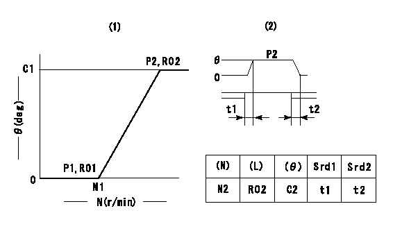
Governor adjustment

(1)Adjusting range
(2)Step response time
(N): Speed of the pump
(L): Load
(theta) Advance angle
(Srd1) Step response time 1
(Srd2) Step response time 2
1. Adjusting conditions for the variable timer
(1)Adjust the clearance between the pickup and the protrusion to L.
----------
L=1-0.2mm N2=800r/min C2=(10deg) t1=2.5--sec. t2=2.5--sec.
----------
N1=750++r/min P1=0kPa(0kgf/cm2) P2=392kPa(4kgf/cm2) C1=10+-0.3deg R01=0/4load R02=4/4load
----------
L=1-0.2mm N2=800r/min C2=(10deg) t1=2.5--sec. t2=2.5--sec.
----------
N1=750++r/min P1=0kPa(0kgf/cm2) P2=392kPa(4kgf/cm2) C1=10+-0.3deg R01=0/4load R02=4/4load
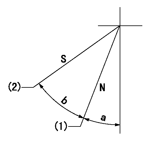
Speed control lever angle

N:Pump normal
S:Stop the pump.
(1)Rack position = aa
(2)Rack position bb
----------
aa=16mm bb=1mm
----------
a=12deg+-5deg b=29deg+-5deg
----------
aa=16mm bb=1mm
----------
a=12deg+-5deg b=29deg+-5deg
0000000901

(1)Pump vertical direction
(2)Coupling's key groove position at No 1 cylinder's beginning of injection
(3)B.T.D.C.: aa
(4)-
----------
aa=4deg
----------
a=(50deg)
----------
aa=4deg
----------
a=(50deg)
Stop lever angle

(Rs) rack sensor specifications
(C/U) control unit part number
(V) Rack sensor output voltage
(R) Rack position (mm)
1. Confirming governor output characteristics (rack 15 mm, span 6 mm)
(1)When the output voltages of the rack sensor are V1 and V2, check that the rack positions R1 and R2 in the table above are satisfied.
----------
----------
----------
----------
0000001201 RACK SENSOR

(VR) measurement voltage
(I) Part number of the control unit
(G) Apply red paint.
(H): End surface of the pump
1. Rack sensor adjustment (154610-0620)
(1)At governor side rack sensor output voltage V1, adjust the bobbin (A) so that the drive side rack sensor output voltage is VR+-0.01.
(2)Apply G at two places.
Connecting part between the joint (B) and the nut (F)
Connecting part between the joint (B) and the end surface of the pump (H)
----------
V1=1V
----------
----------
V1=1V
----------
Information:
Oil Consumption as an Overhaul Indicator
When an engine's oil consumption has risen to three times the initial (new) consumption rate due to normal wear, then the engine should be scheduled for overhaul. There may be a corresponding increase in blowby and a slight increase in fuel consumption.Overhaul Before Failure
A planned Overhaul Before Failure may be your best value, because you can:* Avoid costly unplanned downtime.* Reuse as many original parts as standards permit.* Extend your engine's service life without the risk of a major catastrophe had you continued to operate to failure.* Get the best cost/value relationship per hour of extended life.After Failure Overhaul
If you experience a major engine failure which requires removal of the engine from the hull, there are also many After Failure Overhaul options available. An overhaul should be performed if your block or crankshaft needs to be repaired.If the block and/or crankshaft is repairable, overhaul cost should be between 40 and 50 percent of the cost of a new engine (with like exchange core).This lower cost can be attributed to Caterpillar "designed-in" features, Caterpillar dealer and Caterpillar Remanufactured exchange components.Overhaul Recommendation
To minimize downtime and provide you with the lowest cost and highest value, Caterpillar recommends that the engine be overhauled before failure by scheduling an overhaul with your Caterpillar dealer. Overhaul programs vary with engine application and from dealer to dealer. Therefore, Caterpillar recommends that you confer with your dealer to obtain specific information regarding the types of programs offered and overhaul services provided for extending the life of your engine.If you elect to perform an overhaul without Caterpillar dealer overhaul service, you should be aware of the maintenance that follows.Inspect/Rebuild or Exchange
Cylinder Head, Connecting Rods, Pistons, Cylinder Liners, Turbocharger, Oil Pump, Spacer Plates, Fuel Ratio Control, Cam Followers, Fuel Transfer Pump, and Timing Advance.
These components should be inspected according to the instructions found in various Caterpillar reusability publications. The Index of Publications on Reusability or Salvage of Used Parts, SEBF8029, lists reusability publications needed for inspecting parts.If your parts comply with established inspection specifications expressed in the reusable parts guideline, the parts should be reused.If your parts are not within specification, the parts should be salvaged, repaired, replaced. Failure to salvage, repair, or replace out-of-spec parts can result in unscheduled downtime, costly repairs, and damage to other engine parts.In addition, using out-of-spec parts can reduce your engine's efficiency and increase fuel consumption. Reduced engine efficiency and increase fuel consumption. Reduced engine efficiency and increased fuel consumption translates into higher operating costs. Therefore, Caterpillar recommends that you salvage, repair, or replace your out-of-spec parts.Install New
Piston Rings, Main Bearings, Rod Bearings, Valve Rotators and Crankshaft Seals.
Your thrust, main, and rod bearings, valve rotators, and crankshaft seals will probably not last until your second overhaul. Caterpillar recommends the installation of new parts at each overhaul period.Inspect/Replace
Crankshaft, Camshaft, and Cam Bearings, Crankshaft Vibration Damper, Governor, Fuel Pump Camshaft, and Fuel Racks.
The ideal time for inspecting these items is while your engine is disassembled for overhaul. Inspect each
Have questions with 106873-7480?
Group cross 106873-7480 ZEXEL
Mitsubishi
Mitsubishi
Mitsubishi
Mitsubishi
106873-7480
9 400 611 043
ME094508
INJECTION-PUMP ASSEMBLY
8DC9
8DC9