Information injection-pump assembly
BOSCH
9 400 618 493
9400618493
ZEXEL
106873-7470
1068737470
MITSUBISHI
ME094475
me094475
Rating:
Cross reference number
BOSCH
9 400 618 493
9400618493
ZEXEL
106873-7470
1068737470
MITSUBISHI
ME094475
me094475
Zexel num
Bosch num
Firm num
Name
106873-7470
9 400 618 493
ME094475 MITSUBISHI
INJECTION-PUMP ASSEMBLY
8DC9 K
8DC9 K
Calibration Data:
Adjustment conditions
Test oil
1404 Test oil ISO4113 or {SAEJ967d}
1404 Test oil ISO4113 or {SAEJ967d}
Test oil temperature
degC
40
40
45
Nozzle and nozzle holder
105780-8140
Bosch type code
EF8511/9A
Nozzle
105780-0000
Bosch type code
DN12SD12T
Nozzle holder
105780-2080
Bosch type code
EF8511/9
Opening pressure
MPa
17.2
Opening pressure
kgf/cm2
175
Injection pipe
Outer diameter - inner diameter - length (mm) mm 8-3-600
Outer diameter - inner diameter - length (mm) mm 8-3-600
Overflow valve
134424-1320
Overflow valve opening pressure
kPa
157
123
191
Overflow valve opening pressure
kgf/cm2
1.6
1.25
1.95
Tester oil delivery pressure
kPa
157
157
157
Tester oil delivery pressure
kgf/cm2
1.6
1.6
1.6
Direction of rotation (viewed from drive side)
Right R
Right R
Injection timing adjustment
Direction of rotation (viewed from drive side)
Right R
Right R
Injection order
1-2-7-3-
4-5-6-8
Pre-stroke
mm
4.8
4.75
4.85
Beginning of injection position
Governor side NO.1
Governor side NO.1
Difference between angles 1
Cyl.1-2 deg. 45 44.5 45.5
Cyl.1-2 deg. 45 44.5 45.5
Difference between angles 2
Cal 1-7 deg. 90 89.5 90.5
Cal 1-7 deg. 90 89.5 90.5
Difference between angles 3
Cal 1-3 deg. 135 134.5 135.5
Cal 1-3 deg. 135 134.5 135.5
Difference between angles 4
Cal 1-4 deg. 180 179.5 180.5
Cal 1-4 deg. 180 179.5 180.5
Difference between angles 5
Cal 1-5 deg. 225 224.5 225.5
Cal 1-5 deg. 225 224.5 225.5
Difference between angles 6
Cal 1-6 deg. 270 269.5 270.5
Cal 1-6 deg. 270 269.5 270.5
Difference between angles 7
Cal 1-8 deg. 315 314.5 315.5
Cal 1-8 deg. 315 314.5 315.5
Injection quantity adjustment
Adjusting point
-
Rack position
9.3
Pump speed
r/min
700
700
700
Each cylinder's injection qty
mm3/st.
112.5
109.1
115.9
Basic
*
Fixing the rack
*
Standard for adjustment of the maximum variation between cylinders
*
Injection quantity adjustment_02
Adjusting point
C
Rack position
6.1+-0.5
Pump speed
r/min
225
225
225
Each cylinder's injection qty
mm3/st.
20
17
23
Fixing the rack
*
Standard for adjustment of the maximum variation between cylinders
*
Injection quantity adjustment_03
Adjusting point
A
Rack position
R1(9.3)
Pump speed
r/min
700
700
700
Average injection quantity
mm3/st.
112.5
111.5
113.5
Basic
*
Fixing the lever
*
Injection quantity adjustment_04
Adjusting point
B
Rack position
R1(9.3)
Pump speed
r/min
1100
1100
1100
Average injection quantity
mm3/st.
118.5
113.3
123.7
Difference in delivery
mm3/st.
10.4
10.4
10.4
Fixing the lever
*
Injection quantity adjustment_05
Adjusting point
E
Rack position
-
Pump speed
r/min
100
100
100
Average injection quantity
mm3/st.
140
100
180
Fixing the lever
*
Remarks
After startup boost setting
After startup boost setting
Timer adjustment
Pump speed
r/min
550--
Advance angle
deg.
0
0
0
Remarks
Start
Start
Timer adjustment_02
Pump speed
r/min
500
Advance angle
deg.
0.5
Timer adjustment_03
Pump speed
r/min
1100
Advance angle
deg.
5
4.5
5.5
Remarks
Finish
Finish
Test data Ex:
Governor adjustment
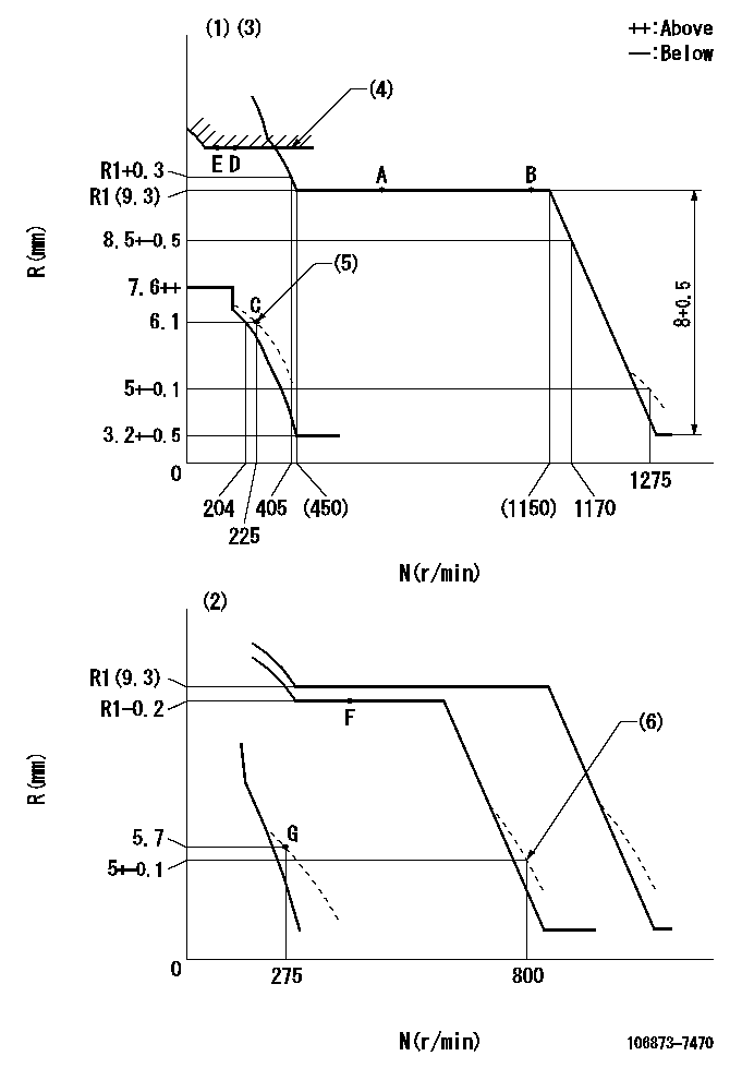
N:Pump speed
R:Rack position (mm)
(1)Adjust with speed control lever at full position (minimum-maximum speed specification)
(2)Adjust with the load control lever in the full position (variable speed specification).
(3)Tolerance for racks not indicated: +-0.05mm.
(4)Excess fuel setting for starting: SXL
(5)Damper spring setting
(6)When air cylinder is operating.
----------
SXL=12+-0.1mm
----------
----------
SXL=12+-0.1mm
----------
Speed control lever angle
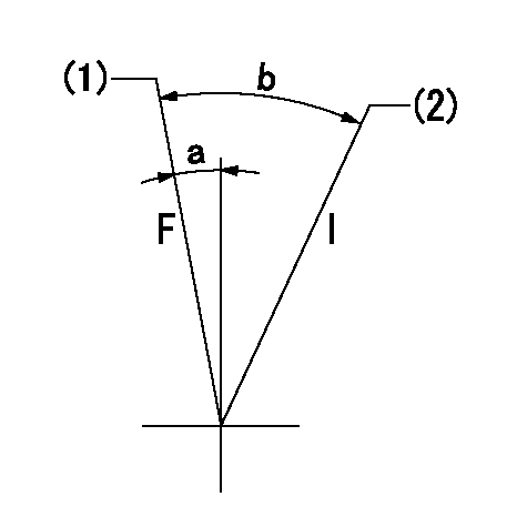
F:Full speed
I:Idle
(1)Pump speed = aa
(2)Pump speed = bb
----------
aa=1275r/min bb=275r/min
----------
a=(5deg)+-5deg b=(14.5deg)+-5deg
----------
aa=1275r/min bb=275r/min
----------
a=(5deg)+-5deg b=(14.5deg)+-5deg
0000000901
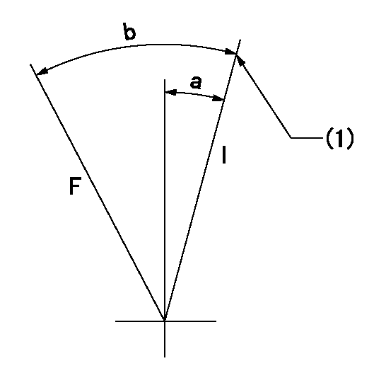
F:Full load
I:Idle
(1)Stopper bolt setting
----------
----------
a=10deg+-5deg b=23deg+-3deg
----------
----------
a=10deg+-5deg b=23deg+-3deg
Stop lever angle

S:Stop the pump.
(1)Rack position = aa
(2)Stopper bolt setting
(3)Free (at delivery)
----------
aa=4-0.5mm
----------
a=10.5deg+-5deg b=56deg+7deg-5deg
----------
aa=4-0.5mm
----------
a=10.5deg+-5deg b=56deg+7deg-5deg
0000001501 MICRO SWITCH
Adjustment of the micro-switch
Adjust the bolt to obtain the following lever position when the micro-switch is ON.
(1)Speed N1
(2)Rack position Ra
----------
N1=325r/min Ra=5.6+-0.1mm
----------
----------
N1=325r/min Ra=5.6+-0.1mm
----------
0000001601 2-STAGE CHANGEOVER DEVICE

RFD governor 2 stage changeover mechanism adjustment outline
(A) Bolt
(B) bolt
(c) Nut
(D) Return spring
(E) Bolt
(F) Bolt
(G) Screw
(H) Bolt
(I) Load lever
(J) Speed lever
(K) Air cylinder
(M Air inlet
Figure 1 is only for reference. Lever shape, etc, may vary.
1. Minimum-maximum speed specification adjustment (when running)
(a) Without applying air to the air cylinder, loosen bolts (A) and (B).
(1)High speed return L setting
(a) In the speed range Nf~Nf - 300r/min, adjust using the speed adjusting bolt to determine the temporary beginning of high speed control speed.
(b) Determine the rack position in the vicinity of Rf using the full load lever.
(c) Increase speed and confirm return distance L.
(d) Adjust using the tension lever bolt to obtain L.
(2)Setting full load rack position Rf
(a) Move the load control lever to the full side.
(b) Adjust the full load adjusting bolt so that Rf can be obtained, then fix.
(3)Setting the beginning of high speed operation Nf
(a) Adjust using bolt (E) so that Nf can be obtained, and then fix.
(4)Idle control setting (Re, Ni, Rc)
(a) Set the speed at Ns + 200r/min and move the load control lever to the idle side.
(b) Fix the lever in the position where Re can be obtained.
(c) Next, decrease speed to Ni and screw in the idle spring.
(d) Adjust to obtain rack position Ri.
(e) Increase the speed and after confirming that the rack position is Re at Ns, set the speed at 0.
(f) Confirm protrusion position Rc at idle.
(5)Damper spring adjustment
(a) Increase speed and set the speed at the rack position Rd - 0.1 mm
(b) Set using the damper spring so that the rack position Rd can be obtained.
(c) When Rd is not specified, Rd = Ri - 0.5 mm.
(6)High speed droop confirmation
(a) Return the load control lever to the full load lever position.
(b) Increase the speed and confirm that Rf can be obtained at Nf r/min.
(c) Confirm that speed is Nh at rack position Rh.
2. Variable speed specification adjustment (at operation)
(a) Remove return spring (D).
(b) Apply air pressure of 245~294 kPa {2.5~3 kg/cm2} to the air cylinder.
(c) Perform the following adjustment in this condition.
(1)Setting full load rack position Rf'
(a) Pull the load lever to the idle side.
(b) Obtain rack position Rf' using the nut (C). (Pump speed is Nf'-50 r/min.)
(2)Setting full speed Nf'
(a) Adjust using bolt (B) so that Nf can be obtained, and then fix.
(3)Low speed side setting
(a) At 350r/min, set bolt (F) at beginning of governor operation position, then fix.
3. Bolt (A) adjustment
(1)Install return spring (D) and perform the adjustments below at air pressure 0.
(a) Set at speed Nf using bolt (E).
(b) Screw in bolt (A).
(c) Screw in 1 more turn from the speed lever contact position
(d) Fix bolt (A).
(e) At this time confirm that the air cylinder's shaft moves approximately 1 mm towards the governor.
4. Lever operation confirmation using the air cylinder
(1)Apply 588 kPa {6 kg/cm2} air pressure to the air cylinder.
(2)Confirm that the cylinder piston is moved 50 mm by the spring (D).
----------
----------
----------
----------
Timing setting

(1)Pump vertical direction
(2)Coupling's key groove position at No 1 cylinder's beginning of injection
(3)-
(4)-
----------
----------
a=(40deg)
----------
----------
a=(40deg)
Information:
You must read and understand the warnings and instructions contained in the Safety section of this manual, before performing any operation or maintenance procedures.Cooling System
Do not perform this maintenance until you read and understand the material in the Safety and Cooling System Specifications sections of this publication.
Drain/Flush/Replace Coolant (Long Life Coolant/Antifreeze Only)
Caterpillar Long Life Coolant/Antifreeze should be replaced every 6,000 Service Hours or 4 Years, whichever comes first. Only clean water is needed to clean and flush the cooling system when LLCA is drained and replaced.Drain
1. Stop the engine and allow the engine to cool. Loosen the coolant filler cap slowly to relieve any pressure, and remove the cap.2. Remove the radiator drain plug, or open the radiator drain valve (if equipped). Remove the block and oil cooler drain plugs. Remove the drain plug from the bottom of the water pump housing. Allow the coolant to drain.
Dispose of used engine coolant properly or recycle. Various methods have been proposed to reclaim used coolant for reuse in engine cooling systems. The full distillation procedure is the only method acceptable by Caterpillar to reclaim the used coolant. Contact your Caterpillar for information regarding disposal and recycling of used coolant.
For information regarding disposal and recycling of used coolant:Contact Caterpillar Service Technology Group:Outside Illinois: 1-800-542-TOOLInside Illinois: 1-800-541-TOOLCanada: 1-800-523-TOOLFlush
4. Flush the cooling system with clean water to remove any debris.5. Clean and install all drain plugs and/or close the drain valve(s).6. Fill the cooling system with clean water. Install the filler cap. Operate the engine until warm 49 to 66°C (150 to 120°F).7. Stop the engine and allow the engine to cool. Loosen the coolant filler cap slowly to relieve any pressure, and remove the cap. Remove the cooling system drain plug(s) or open the drain valve. Allow the water to drain. Flush the cooling system with clean water.8. Repeat steps 6 and 7.Fill
9. Fill the cooling system with LLCA. Refer to the refill capacities chart in this manual for the amount of LLCA needed to refill your system.10. Start and run the engine with the filler cap removed. Allow the LLCA to warm, the thermostat to open, and the coolant level to stabilize. Add LLCA if necessary to bring the coolant to the proper level.11. Check the condition of the filler cap gasket. If the gasket is damaged, discard the old filler cap and install a new filler cap. If the gasket is not damaged, use a 9S8140 Service Tool (available from your Caterpillar dealer) to pressure test the filler cap. The correct filler cap pressure is stamped on the face of the filler cap. If the filler cap does not hold the correct pressure, install a new filler cap.12. Start the engine and inspect for coolant leaks and proper operating temperature.
Have questions with 106873-7470?
Group cross 106873-7470 ZEXEL
Mitsubishi
Mitsubishi
Mitsubishi
Mitsubishi
106873-7470
9 400 618 493
ME094475
INJECTION-PUMP ASSEMBLY
8DC9
8DC9