Information injection-pump assembly
BOSCH
9 400 618 480
9400618480
ZEXEL
106873-7260
1068737260
MITSUBISHI
ME094010
me094010
Rating:
Cross reference number
BOSCH
9 400 618 480
9400618480
ZEXEL
106873-7260
1068737260
MITSUBISHI
ME094010
me094010
Zexel num
Bosch num
Firm num
Name
Calibration Data:
Adjustment conditions
Test oil
1404 Test oil ISO4113 or {SAEJ967d}
1404 Test oil ISO4113 or {SAEJ967d}
Test oil temperature
degC
40
40
45
Nozzle and nozzle holder
105780-8250
Bosch type code
1 688 901 101
Nozzle
105780-0120
Bosch type code
1 688 901 990
Nozzle holder
105780-2190
Opening pressure
MPa
20.7
Opening pressure
kgf/cm2
211
Injection pipe
Outer diameter - inner diameter - length (mm) mm 8-3-600
Outer diameter - inner diameter - length (mm) mm 8-3-600
Overflow valve
131425-0220
Overflow valve opening pressure
kPa
157
123
191
Overflow valve opening pressure
kgf/cm2
1.6
1.25
1.95
Tester oil delivery pressure
kPa
255
255
255
Tester oil delivery pressure
kgf/cm2
2.6
2.6
2.6
RED3 control unit part number
407910-2
470
RED3 rack sensor specifications
mm
15
Direction of rotation (viewed from drive side)
Right R
Right R
Injection timing adjustment
Direction of rotation (viewed from drive side)
Right R
Right R
Injection order
1-2-7-3-
4-5-6-8
Pre-stroke
mm
3.9
3.85
3.95
Beginning of injection position
Governor side NO.1
Governor side NO.1
Difference between angles 1
Cyl.1-2 deg. 45 44.5 45.5
Cyl.1-2 deg. 45 44.5 45.5
Difference between angles 2
Cal 1-7 deg. 90 89.5 90.5
Cal 1-7 deg. 90 89.5 90.5
Difference between angles 3
Cal 1-3 deg. 135 134.5 135.5
Cal 1-3 deg. 135 134.5 135.5
Difference between angles 4
Cal 1-4 deg. 180 179.5 180.5
Cal 1-4 deg. 180 179.5 180.5
Difference between angles 5
Cal 1-5 deg. 225 224.5 225.5
Cal 1-5 deg. 225 224.5 225.5
Difference between angles 6
Cal 1-6 deg. 270 269.5 270.5
Cal 1-6 deg. 270 269.5 270.5
Difference between angles 7
Cal 1-8 deg. 315 314.5 315.5
Cal 1-8 deg. 315 314.5 315.5
Injection quantity adjustment
Rack position
(10.7)
Vist
V
1.86
1.86
1.86
Pump speed
r/min
700
700
700
Average injection quantity
mm3/st.
125
124
126
Max. variation between cylinders
%
0
-3
3
Basic
*
Injection quantity adjustment_02
Rack position
(6.5)
Vist
V
2.7
2.6
2.8
Pump speed
r/min
380
380
380
Average injection quantity
mm3/st.
16
14
18
Max. variation between cylinders
%
0
-15
15
Test data Ex:
Governor adjustment

(1)Adjusting range
(2)Step response time
(N): Speed of the pump
(L): Load
(theta) Advance angle
(Srd1) Step response time 1
(Srd2) Step response time 2
1. Adjusting conditions for the variable timer
(1)Adjust the clearance between the pickup and the protrusion to L.
----------
L=1-0.2mm N2=800r/min C2=(10deg) t1=2.5--sec. t2=2.5--sec.
----------
N1=750++r/min P1=0kPa(0kgf/cm2) P2=392kPa(4kgf/cm2) C1=10+-0.3deg R01=0/4load R02=4/4load
----------
L=1-0.2mm N2=800r/min C2=(10deg) t1=2.5--sec. t2=2.5--sec.
----------
N1=750++r/min P1=0kPa(0kgf/cm2) P2=392kPa(4kgf/cm2) C1=10+-0.3deg R01=0/4load R02=4/4load
Speed control lever angle
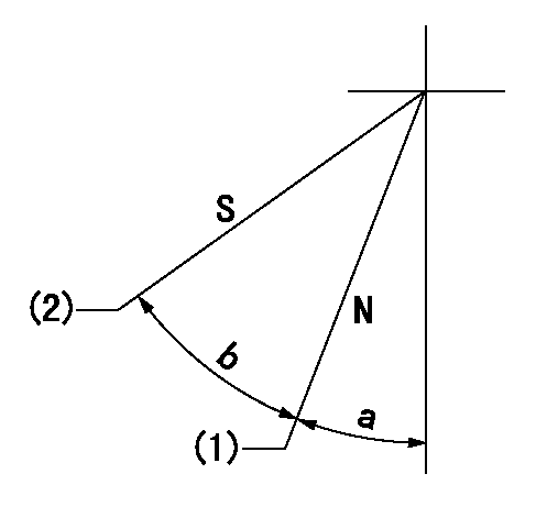
N:Pump normal
S:Stop the pump.
(1)Rack position = aa
(2)Rack position bb
----------
aa=16mm bb=1mm
----------
a=26deg+-5deg b=29deg+-5deg
----------
aa=16mm bb=1mm
----------
a=26deg+-5deg b=29deg+-5deg
0000000901

(1)Pump vertical direction
(2)Coupling's key groove position at No 1 cylinder's beginning of injection
(3)B.T.D.C.: aa
(4)-
----------
aa=4deg
----------
a=(50deg)
----------
aa=4deg
----------
a=(50deg)
Stop lever angle

(Rs) rack sensor specifications
(C/U) control unit part number
(V) Rack sensor output voltage
(R) Rack position (mm)
1. Confirming governor output characteristics (rack 15 mm, span 6 mm)
(1)When the output voltages of the rack sensor are V1 and V2, check that the rack positions R1 and R2 in the table above are satisfied.
----------
----------
----------
----------
0000001201 RACK SENSOR

(VR) measurement voltage
(I) Part number of the control unit
(G) Apply red paint.
(H): End surface of the pump
1. Rack sensor adjustment (154610-0620)
(1)At governor side rack sensor output voltage V1, adjust the bobbin (A) so that the drive side rack sensor output voltage is VR+-0.01.
(2)Apply G at two places.
Connecting part between the joint (B) and the nut (F)
Connecting part between the joint (B) and the end surface of the pump (H)
----------
V1=1V
----------
----------
V1=1V
----------
Information:
Proper operation and maintenance are key factors in obtaining the maximum life and economy of the engine. Following the directions in this Manual will lower operating costs.The time needed for the engine to reach the normal mode of operation is usually less than the time taken for a walk-around inspection of the engine. After the engine is started and the cold low speed operation is completed, the engine can be operated at rated speed and low power. The engine will reach normal operating temperature faster when operated at low power demand than when idled at no load. Typically the engine should reach operating temperature in a few minutes.Normal Mode
The electronic governor/control (ECM) system provides complete engine speed governing and controls cold start mode strategies, torque shaping, smoke limiting, system diagnostics and communication data links to monitor performance and diagnostic information. Warning outputs are provided for low oil pressure, low boost pressure, high coolant temperature and low coolant level with a diagnostic lamp.The purpose of normal mode is to monitor and control the genset. The GSC controls the engine according to the information received from the operator (panel switches, controls) and from the engine sensors. Some of the functions performed by the GSC while in normal mode are: engine starting, monitoring of important genset conditions, showing the operator the important genset conditions, fault detection, and engine stopping.The operator can identify normal mode by observing the display area. When in normal mode: all shutdown indicators are OFF, the fault alarm indicator is OFF and SERV is NOT displayed on the upper window. When the GSC is in normal mode, the engine is able to start or run. Refer to Engine Control, Monitoring and Protection topic for information regarding GSC control panel. In the AUTOmatic position (3 o'clock), the engine will start automatically whenever a remote initiating contact is closed. The engine will shutdown after the initiating contact opens and adjustable cooldown time elapsed. The cooldown time can be programmed to give a 0 to 30 minute cooldown period before the engine shuts down.In the MAN. START position (6 o'clock), the engine will start and run as long as the ECS switch remains in this position. In the COOLDOWN STOP position (9 o'clock), the fuel solenoid shuts the engine down, after a programmable cool down time period. In the OFF/RESET position (12 o'clock), the fault lights are reset and the engine shuts down immediately.1. Do not apply a load to the engine, or increase the speed until the oil pressure indicates normal. 2. Move the Manual Speed Potentiometer (MSP) to the (high idle-full load) position. 3. Apply the load to the driven equipment.4. Manually turn the MSP adjusting knob to change engine speed. To adjust or change engine speed droop setting, use the speed droop set screw. Control Panel Equipped Engines-Starting, Operating and Stopping
For all information regarding the generator control panel used for starting, operating and stopping the engine, refer to SR4 Generators and Control Panels Operation & Maintenance