Information injection-pump assembly
BOSCH
9 400 618 477
9400618477
ZEXEL
106873-7220
1068737220
MITSUBISHI
ME093735
me093735
Rating:
Cross reference number
BOSCH
9 400 618 477
9400618477
ZEXEL
106873-7220
1068737220
MITSUBISHI
ME093735
me093735
Zexel num
Bosch num
Firm num
Name
106873-7220
9 400 618 477
ME093735 MITSUBISHI
INJECTION-PUMP ASSEMBLY
8DC9 * K
8DC9 * K
Calibration Data:
Adjustment conditions
Test oil
1404 Test oil ISO4113 or {SAEJ967d}
1404 Test oil ISO4113 or {SAEJ967d}
Test oil temperature
degC
40
40
45
Nozzle and nozzle holder
105780-8140
Bosch type code
EF8511/9A
Nozzle
105780-0000
Bosch type code
DN12SD12T
Nozzle holder
105780-2080
Bosch type code
EF8511/9
Opening pressure
MPa
17.2
Opening pressure
kgf/cm2
175
Injection pipe
Outer diameter - inner diameter - length (mm) mm 8-3-600
Outer diameter - inner diameter - length (mm) mm 8-3-600
Overflow valve
134424-1320
Overflow valve opening pressure
kPa
157
123
191
Overflow valve opening pressure
kgf/cm2
1.6
1.25
1.95
Tester oil delivery pressure
kPa
157
157
157
Tester oil delivery pressure
kgf/cm2
1.6
1.6
1.6
Direction of rotation (viewed from drive side)
Right R
Right R
Injection timing adjustment
Direction of rotation (viewed from drive side)
Right R
Right R
Injection order
1-2-7-3-
4-5-6-8
Pre-stroke
mm
4.8
4.75
4.85
Beginning of injection position
Governor side NO.1
Governor side NO.1
Difference between angles 1
Cyl.1-2 deg. 45 44.5 45.5
Cyl.1-2 deg. 45 44.5 45.5
Difference between angles 2
Cal 1-7 deg. 90 89.5 90.5
Cal 1-7 deg. 90 89.5 90.5
Difference between angles 3
Cal 1-3 deg. 135 134.5 135.5
Cal 1-3 deg. 135 134.5 135.5
Difference between angles 4
Cal 1-4 deg. 180 179.5 180.5
Cal 1-4 deg. 180 179.5 180.5
Difference between angles 5
Cal 1-5 deg. 225 224.5 225.5
Cal 1-5 deg. 225 224.5 225.5
Difference between angles 6
Cal 1-6 deg. 270 269.5 270.5
Cal 1-6 deg. 270 269.5 270.5
Difference between angles 7
Cal 1-8 deg. 315 314.5 315.5
Cal 1-8 deg. 315 314.5 315.5
Injection quantity adjustment
Adjusting point
-
Rack position
9.3
Pump speed
r/min
700
700
700
Each cylinder's injection qty
mm3/st.
112.5
109.1
115.9
Basic
*
Fixing the rack
*
Standard for adjustment of the maximum variation between cylinders
*
Injection quantity adjustment_02
Adjusting point
C
Rack position
6.1+-0.5
Pump speed
r/min
225
225
225
Each cylinder's injection qty
mm3/st.
20
17
23
Fixing the rack
*
Standard for adjustment of the maximum variation between cylinders
*
Injection quantity adjustment_03
Adjusting point
A
Rack position
R1(9.3)
Pump speed
r/min
700
700
700
Average injection quantity
mm3/st.
112.5
111.5
113.5
Basic
*
Fixing the lever
*
Injection quantity adjustment_04
Adjusting point
B
Rack position
R1(9.3)
Pump speed
r/min
1100
1100
1100
Average injection quantity
mm3/st.
118.5
113.3
123.7
Difference in delivery
mm3/st.
10.4
10.4
10.4
Fixing the lever
*
Injection quantity adjustment_05
Adjusting point
E
Rack position
-
Pump speed
r/min
100
100
100
Average injection quantity
mm3/st.
140
120
160
Fixing the lever
*
Remarks
After startup boost setting
After startup boost setting
Timer adjustment
Pump speed
r/min
550--
Advance angle
deg.
0
0
0
Remarks
Start
Start
Timer adjustment_02
Pump speed
r/min
500
Advance angle
deg.
0.5
Timer adjustment_03
Pump speed
r/min
1100
Advance angle
deg.
5
4.5
5.5
Remarks
Finish
Finish
Test data Ex:
Governor adjustment
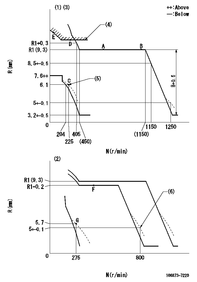
N:Pump speed
R:Rack position (mm)
(1)Adjust with speed control lever at full position (minimum-maximum speed specification)
(2)Adjust with the load control lever in the full position (variable speed specification).
(3)Tolerance for racks not indicated: +-0.05mm.
(4)Excess fuel setting for starting: SXL
(5)Damper spring setting
(6)When air cylinder is operating.
----------
SXL=10.2+-0.1mm
----------
----------
SXL=10.2+-0.1mm
----------
Speed control lever angle
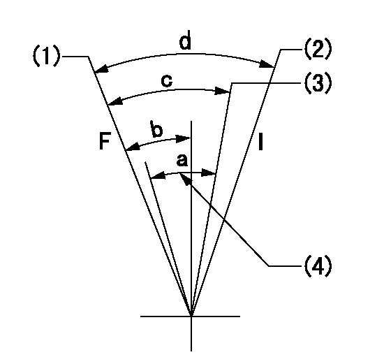
F:Full speed
I:Idle
(1)Pump speed = aa
(2)Pump speed = bb
(3)Pump speed cc
(4)Air cylinder's adjustable range
----------
aa=1250r/min bb=275r/min cc=800r/min
----------
a=(7deg) b=4.5deg+-5deg c=(7deg)+-5deg d=(12deg)+-5deg
----------
aa=1250r/min bb=275r/min cc=800r/min
----------
a=(7deg) b=4.5deg+-5deg c=(7deg)+-5deg d=(12deg)+-5deg
0000000901

F:Full load
I:Idle
(1)Stopper bolt setting
----------
----------
a=10deg+-5deg b=23deg+-3deg
----------
----------
a=10deg+-5deg b=23deg+-3deg
Stop lever angle
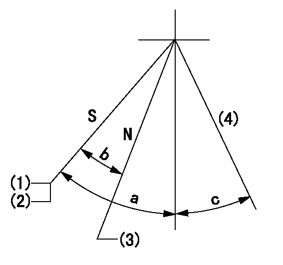
N:Engine manufacturer's normal use
S:Stop the pump.
(1)Rack position = aa
(2)Stopper bolt setting
(3)Rack position bb
(4)Free (at delivery)
----------
aa=4-0.5mm bb=11.7mm
----------
a=45.5deg+7deg-5deg b=22deg+-5deg c=(10.5deg)
----------
aa=4-0.5mm bb=11.7mm
----------
a=45.5deg+7deg-5deg b=22deg+-5deg c=(10.5deg)
0000001501 2-STAGE CHANGEOVER DEVICE

RFD governor 2 stage changeover mechanism adjustment outline
(A) Bolt
(B) bolt
(c) Nut
(D) Return spring
(E) Bolt
(F) Bolt
(G) Screw
(H) Bolt
(I) Load lever
(J) Speed lever
(K) Air cylinder
(M Air inlet
Figure 1 is only for reference. Lever shape, etc, may vary.
1. Minimum-maximum speed specification adjustment (when running)
(a) Without applying air to the air cylinder, loosen bolts (A) and (B).
(1)High speed return L setting
(a) In the speed range Nf~Nf - 300r/min, adjust using the speed adjusting bolt to determine the temporary beginning of high speed control speed.
(b) Determine the rack position in the vicinity of Rf using the full load lever.
(c) Increase speed and confirm return distance L.
(d) Adjust using the tension lever bolt to obtain L.
(2)Setting full load rack position Rf
(a) Move the load control lever to the full side.
(b) Adjust the full load adjusting bolt so that Rf can be obtained, then fix.
(3)Setting the beginning of high speed operation Nf
(a) Adjust using bolt (E) so that Nf can be obtained, and then fix.
(4)Idle control setting (Re, Ni, Rc)
(a) Set the speed at Ns + 200r/min and move the load control lever to the idle side.
(b) Fix the lever in the position where Re can be obtained.
(c) Next, decrease speed to Ni and screw in the idle spring.
(d) Adjust to obtain rack position Ri.
(e) Increase the speed and after confirming that the rack position is Re at Ns, set the speed at 0.
(f) Confirm protrusion position Rc at idle.
(5)Damper spring adjustment
(a) Increase speed and set the speed at the rack position Rd - 0.1 mm
(b) Set using the damper spring so that the rack position Rd can be obtained.
(c) When Rd is not specified, Rd = Ri - 0.5 mm.
(6)High speed droop confirmation
(a) Return the load control lever to the full load lever position.
(b) Increase the speed and confirm that Rf can be obtained at Nf r/min.
(c) Confirm that speed is Nh at rack position Rh.
2. Variable speed specification adjustment (at operation)
(a) Remove return spring (D).
(b) Apply air pressure of 245~294 kPa {2.5~3 kg/cm2} to the air cylinder.
(c) Perform the following adjustment in this condition.
(1)Setting full load rack position Rf'
(a) Pull the load lever to the idle side.
(b) Obtain rack position Rf' using the nut (C). (Pump speed is Nf'-50 r/min.)
(2)Setting full speed Nf'
(a) Adjust using bolt (B) so that Nf can be obtained, and then fix.
(3)Low speed side setting
(a) At 350r/min, set bolt (F) at beginning of governor operation position, then fix.
3. Bolt (A) adjustment
(1)Install return spring (D) and perform the adjustments below at air pressure 0.
(a) Set at speed Nf using bolt (E).
(b) Screw in bolt (A).
(c) Screw in 1 more turn from the speed lever contact position
(d) Fix bolt (A).
(e) At this time confirm that the air cylinder's shaft moves approximately 1 mm towards the governor.
4. Lever operation confirmation using the air cylinder
(1)Apply 588 kPa {6 kg/cm2} air pressure to the air cylinder.
(2)Confirm that the cylinder piston is moved 50 mm by the spring (D).
----------
----------
----------
----------
0000001601 MICRO SWITCH
Adjustment of the micro-switch
Adjust the bolt to obtain the following lever position when the micro-switch is ON.
(1)Speed N1
(2)Rack position Ra
----------
N1=325r/min Ra=5.6+-0.1mm
----------
----------
N1=325r/min Ra=5.6+-0.1mm
----------
0000001701 ACS
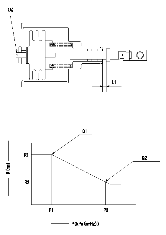
(A) Set screw
1. Aneroid compensator unit adjustment
Screw in (A) to obtain L1.
2. Adjustment following governor installation
(1)Set the speed of the pump to N1 r/min and fix the control lever at the full set position.
(2)Screw in the aneroid compensator to obtain the performance shown in the graph above.
----------
N1=700r/min L1=0.1~0.5mm
----------
R1=R1(9.3)mm R2=R1-0.4mm P1=(97.3)kPa((730)mmHg) P2=84.6+-0.7kPa(635+-5mmHg) Q1=112.5+-1cm3/1000st Q2=(103.1)+-3cm3/1000st
----------
N1=700r/min L1=0.1~0.5mm
----------
R1=R1(9.3)mm R2=R1-0.4mm P1=(97.3)kPa((730)mmHg) P2=84.6+-0.7kPa(635+-5mmHg) Q1=112.5+-1cm3/1000st Q2=(103.1)+-3cm3/1000st
Timing setting

(1)Pump vertical direction
(2)Coupling's key groove position at No 1 cylinder's beginning of injection
(3)-
(4)-
----------
----------
a=(40deg)
----------
----------
a=(40deg)
Information:
Caterpillar Reference Material
The following literature can be obtained through any Caterpillar dealer.Caterpillar Reference Materials for Lubricants
PEHP5026, Data Sheet- Caterpillar Diesel Engine Oils (DEO) (CG4/CF-4) (North America and selected International)PEHP1026, Data Sheet- Caterpillar Diesel Engine Oil (DEO) (CF-4) (International only)PEHP0003, Data Sheet- Multipurpose Lithium Complex Grease (MPG)PEHP0002, Data Sheet- Multipurpose Lithium Complex Grease with Molybdenum (MPGM)PEHP0017, Data Sheet- Special Purpose Grease (SPG) Bearing LubricantPECP4025, One Safe SourceSEBD0640, Oil and Your EngineSEBU5898, Cold Weather RecommendationsPEDP1129, Listen To Your OilCaterpillar Reference Materials for Fuels
SEBD0717, Diesel Fuels and Your EngineCaterpillar Reference Materials for Coolants
PEHP4036, Data Sheet- Caterpillar CoolantPEHP5033, S O S Coolant AnalysisPECP4025, One Safe SourceSEBD0518, Know Your Cooling SystemSEBD0970, Coolant and Your EngineMiscellaneous
SENR7377, Service Manual (99U1-7598)SENR7405, Service Manual (60M1-5160)SENR1160, Service Manual (60M5161-UP, 99U7599-UP)LEBM1091, Caterpillar Worldwide Marine DirectoryLEXM0683, Pleasure Craft Storage GuideLEBM3001, 3400 Marine Propulsion Engine PerformanceSENR3130, Torque SpecificationsSEBF8029, Index to Guidelines for Reusable Parts and Salvage OperationsSEBF8062, Guideline for Reusable Parts - Cleaning and Inspection of Air FiltersSEHS9031, Storage Procedure for Caterpillar ProductsSEHS7292, Use of 5P-4150 Nozzle Testing GroupSEHS7795, Use of Pump & Governor Tool GroupSEHS8024, Governor Adjusting Tool GroupSEHS8094, Use of Nozzle Puller GroupSEHS7633, Battery Test ProcedureSEHS7332, Do Not Operate tagAdditional Reference Material
American Society for Testing and Materials (ASTM) Specifications can normally be obtained from your local technological society, library, or college, or contact:American Society for Testing and Materials
1916 Race St.
Philadelphia, PA 19103
Society of Automotive Engineers (SAE) Specifications can be found in your SAE handbook or can be obtained from your local library, college or technological society, or contact:SAE International
400 Commonwealth Drive
Warrendale, PA USA 15096-0001
Engine Manufacturers Association (EMA) information for lube oil selection can be obtained from your local library, college or technological society, or contact:Engine Manufacturers Association
Lubricating Oils Data Book
401 N. Michigan Ave. Ste. 2400
Chicago, IL 60611
Have questions with 106873-7220?
Group cross 106873-7220 ZEXEL
Mitsubishi
Mitsubishi
106873-7220
9 400 618 477
ME093735
INJECTION-PUMP ASSEMBLY
8DC9
8DC9