Information injection-pump assembly
ZEXEL
106873-7164
1068737164
Rating:
Service parts 106873-7164 INJECTION-PUMP ASSEMBLY:
1.
_
7.
COUPLING PLATE
8.
_
9.
_
11.
Nozzle and Holder
ME093528
12.
Open Pre:MPa(Kqf/cm2)
15.7{160}/21.6{220}
14.
NOZZLE
Include in #1:
106873-7164
as INJECTION-PUMP ASSEMBLY
Cross reference number
ZEXEL
106873-7164
1068737164
Zexel num
Bosch num
Firm num
Name
106873-7164
INJECTION-PUMP ASSEMBLY
14CD PE8P PE
14CD PE8P PE
Calibration Data:
Adjustment conditions
Test oil
1404 Test oil ISO4113 or {SAEJ967d}
1404 Test oil ISO4113 or {SAEJ967d}
Test oil temperature
degC
40
40
45
Nozzle and nozzle holder
105780-8250
Bosch type code
1 688 901 101
Nozzle
105780-0120
Bosch type code
1 688 901 990
Nozzle holder
105780-2190
Opening pressure
MPa
20.7
Opening pressure
kgf/cm2
211
Injection pipe
Outer diameter - inner diameter - length (mm) mm 8-3-600
Outer diameter - inner diameter - length (mm) mm 8-3-600
Overflow valve
131425-0220
Overflow valve opening pressure
kPa
157
123
191
Overflow valve opening pressure
kgf/cm2
1.6
1.25
1.95
Tester oil delivery pressure
kPa
255
255
255
Tester oil delivery pressure
kgf/cm2
2.6
2.6
2.6
Direction of rotation (viewed from drive side)
Right R
Right R
Injection timing adjustment
Direction of rotation (viewed from drive side)
Right R
Right R
Injection order
1-2-7-3-
4-5-6-8
Pre-stroke
mm
3.9
3.85
3.95
Beginning of injection position
Governor side NO.1
Governor side NO.1
Difference between angles 1
Cyl.1-2 deg. 45 44.5 45.5
Cyl.1-2 deg. 45 44.5 45.5
Difference between angles 2
Cal 1-7 deg. 90 89.5 90.5
Cal 1-7 deg. 90 89.5 90.5
Difference between angles 3
Cal 1-3 deg. 135 134.5 135.5
Cal 1-3 deg. 135 134.5 135.5
Difference between angles 4
Cal 1-4 deg. 180 179.5 180.5
Cal 1-4 deg. 180 179.5 180.5
Difference between angles 5
Cal 1-5 deg. 225 224.5 225.5
Cal 1-5 deg. 225 224.5 225.5
Difference between angles 6
Cal 1-6 deg. 270 269.5 270.5
Cal 1-6 deg. 270 269.5 270.5
Difference between angles 7
Cal 1-8 deg. 315 314.5 315.5
Cal 1-8 deg. 315 314.5 315.5
Injection quantity adjustment
Adjusting point
-
Rack position
13.9
Pump speed
r/min
700
700
700
Each cylinder's injection qty
mm3/st.
159
154.2
163.8
Basic
*
Fixing the rack
*
Standard for adjustment of the maximum variation between cylinders
*
Injection quantity adjustment_02
Adjusting point
Z
Rack position
8.6+-0.5
Pump speed
r/min
415
415
415
Each cylinder's injection qty
mm3/st.
19
16.1
21.9
Fixing the rack
*
Standard for adjustment of the maximum variation between cylinders
*
Injection quantity adjustment_03
Adjusting point
A
Rack position
R1(13.9)
Pump speed
r/min
700
700
700
Average injection quantity
mm3/st.
159
158
160
Basic
*
Fixing the lever
*
Boost pressure
kPa
26
26
Boost pressure
mmHg
195
195
Injection quantity adjustment_04
Adjusting point
B
Rack position
R1+1.65
Pump speed
r/min
1100
1100
1100
Average injection quantity
mm3/st.
166.5
162.5
170.5
Fixing the lever
*
Boost pressure
kPa
26
26
Boost pressure
mmHg
195
195
Boost compensator adjustment
Pump speed
r/min
300
300
300
Rack position
R2-1.2
Boost pressure
kPa
6.7
5.4
8
Boost pressure
mmHg
50
40
60
Boost compensator adjustment_02
Pump speed
r/min
300
300
300
Rack position
R2(R1-1.
2)
Boost pressure
kPa
12.7
12.7
12.7
Boost pressure
mmHg
95
95
95
Test data Ex:
Governor adjustment
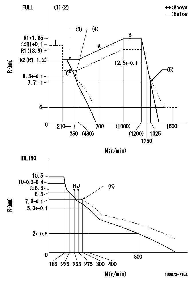
N:Pump speed
R:Rack position (mm)
(1)Torque cam stamping: T1
(2)Tolerance for racks not indicated: +-0.05mm.
(3)Boost compensator stroke: BCL
(4)Air cylinder ON
(5)Air cylinder OFF
(6)Damper spring setting
----------
T1=AC77 BCL=1.2+-0.1mm
----------
----------
T1=AC77 BCL=1.2+-0.1mm
----------
Timer adjustment
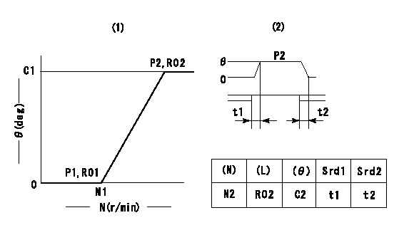
(1)Adjusting range
(2)Step response time
(N): Speed of the pump
(L): Load
(theta) Advance angle
(Srd1) Step response time 1
(Srd2) Step response time 2
1. Adjusting conditions for the variable timer
(1)Adjust the clearance between the pickup and the protrusion to L.
----------
L=1-0.2mm N2=800r/min C2=(10)deg t1=2.5--sec. t2=2.5--sec.
----------
N1=750++r/min P1=0kPa(0kgf/cm2) P2=392kPa(4kgf/cm2) C1=10+-0.3deg R01=0/4load R02=4/4load
----------
L=1-0.2mm N2=800r/min C2=(10)deg t1=2.5--sec. t2=2.5--sec.
----------
N1=750++r/min P1=0kPa(0kgf/cm2) P2=392kPa(4kgf/cm2) C1=10+-0.3deg R01=0/4load R02=4/4load
Speed control lever angle
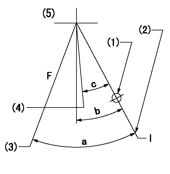
F:Full speed
I:Idle
(1)Use the hole at R = aa
(2)Stopper bolt set position 'H'
(3)When air cylinder OFF.
(4)When air cylinder ON.
(5)Viewed from feed pump side.
----------
aa=37.5mm
----------
a=(39.5deg)+-3deg b=11.5deg+-5deg c=(4.5deg)
----------
aa=37.5mm
----------
a=(39.5deg)+-3deg b=11.5deg+-5deg c=(4.5deg)
Stop lever angle
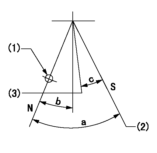
N:Pump normal
S:Stop the pump.
(1)Use the hole at R = aa
(2)Set the stopper bolt so that speed = bb and rack position = cc. (Confirm non-injection.)
(3)Normal engine position (Rack position corresponding to dd)
----------
aa=54mm bb=1100r/min cc=3.5+-0.3mm dd=18mm
----------
a=41deg+-5deg b=5.5deg+-5deg c=(31deg)
----------
aa=54mm bb=1100r/min cc=3.5+-0.3mm dd=18mm
----------
a=41deg+-5deg b=5.5deg+-5deg c=(31deg)
0000001501 MICRO SWITCH
Adjustment of the micro-switch
Adjust the bolt to obtain the following lever position when the micro-switch is ON.
(1)Speed N1
(2)Rack position Ra
----------
N1=325r/min Ra=8.8+-0.1mm
----------
----------
N1=325r/min Ra=8.8+-0.1mm
----------
0000001601 RACK SENSOR
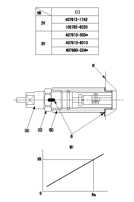
(VR) measurement voltage
(I) Part number of the control unit
(G) Apply red paint.
(H): End surface of the pump
1. Rack sensor adjustment (-0620)
(1)Fix the speed control lever at the full position
(2)Set the speed to N1 r/min.
(If the boost compensator is provided, apply boost pressure.)
(3)Adjust the bobbin (A) so that the rack sensor's output voltage is VR+-0.01.
(4)At that time, rack position must be Ra.
(5)Apply G at two places.
Connecting part between the joint (B) and the nut (F)
Connecting part between the joint (B) and the end surface of the pump (H)
----------
N1=1100r/min Ra=R1(13.9)+1.65mm
----------
----------
N1=1100r/min Ra=R1(13.9)+1.65mm
----------
0000001701 AIR CYLINDER
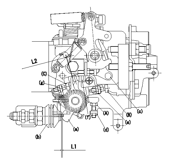
<A> stopper bolt
<B> stopper bolt
<C> stopper bolt
(a) lever
(b) air cylinder
(c) speed lever
(d) Nut
(e) nut
(f) lever
(g) nut
1. Stopper bolt <A> adjustment method
(1)When air cylinder pressure is P1, set the gap between the lever (a) and the air cylinder (b) to L1.
(2)Confirm that the speed lever (c) operates between idling and full speed.
(3)Fix stopper bolt <A> using nut (d).
2. Stopper bolt <B> adjustment method.
(1)At air cylinder pressure P2, pump speed N1 and rack position is R1, adjust stopper bolt (B) so that the speed lever (c) is in the stop position.
(2)Turn the stopper bolt (c) so that the clearance between lever (a) and lever (f) is L2, then fix using nut (g).
(3)Move the lever (a) several times and fix stopper bolt <B> using the nut (e).
(4)Tightening torque T1 for nuts (d), (e) and (g)
----------
L1=1+0.5++mm L2=1+0.5++mm P1=0kPa(0kgf/cm2) P2=392+98kpa(4+1kgf/cm2) N1=350r/min R1=8.5+-0.1mm T1=4.9~6.86N-m(0.5~0.7kgf-m)
----------
----------
L1=1+0.5++mm L2=1+0.5++mm P1=0kPa(0kgf/cm2) P2=392+98kpa(4+1kgf/cm2) N1=350r/min R1=8.5+-0.1mm T1=4.9~6.86N-m(0.5~0.7kgf-m)
----------
Timing setting

(1)Pump vertical direction
(2)Coupling's key groove position at No 1 cylinder's beginning of injection
(3)B.T.D.C.: aa
(4)-
----------
aa=4deg
----------
a=(50deg)
----------
aa=4deg
----------
a=(50deg)
Information:
Contact your Caterpillar dealer for part numbers and available container sizes.
This oil is formulated for transmissions and drive trains only, and should not be used in engines. Shortened engine service life will result.Do not use Caterpillar Gear Oil (GO) in marine transmissions. Gear Oil can cause seal material to fail and possibly leak. Gear Oil also may not be compatible with friction materials and can reduce transmission efficiency.
Multi-grade oils are not currently blended by Caterpillar for use in transmissions. Multi-grade oils which use high molecular weight polymers as viscosity index improvers lose their viscosity effectiveness by permanent and temporary shear of the viscosity index improver. Therefore, multi-grade oils are not recommended for transmissions. The Caterpillar TO-4 specification does include a test for multi-grade oil shear stability. Multi-grade oils with adequate shear stability may be available in the future.Commercial Transmission/Drive Train Oils
If Caterpillar Transmission/Drive Train Oil is not used, commercial oils meeting the Caterpillar TO-4 specification must be used in Caterpillar marine transmissions:* TO-4 Specification Oils, single grade onlyCommercial Marine Transmissions
For marine transmissions which are not manufactured by Caterpillar, refer to the marine transmission or vessel OEM lubrication recommendations.S O S Oil Analysis
Caterpillar's Scheduled Oil Sampling (S O S) Oil Analysis should be a part of an engine's overall maintenance program. The S O S program monitors the engine and transmission through used oil analysis. The oil analysis measures wear metals and oil condition. Deviations from established limits or trend lines can diagnose an impending problem before the problem becomes apparent, costly, and destructive.See your Caterpillar dealer for more information regarding S O S Oil Analysis and how the program can help you manage your engine and transmission.Engine Lubricant Recommendations Summary
To achieve all the performance that was built into a Caterpillar engine, follow these guidelines:* Select the proper Caterpillar oil or commercial oil that meets the API specifications* Select the proper oil viscosity based on the applicable Lubricant Viscosities chart* Replace the engine oil and oil filter(s) at the intervals specified in the Operation and Maintenance Manual* Perform maintenance according to the Operation and Maintenance ManualCaterpillar Lubricating Grease
Caterpillar provides grease for a variety of applications and extreme temperature conditions. The descriptions of these products follow.Contact your Caterpillar dealer for part numbers and available container sizes. One grease may be incompatible with another grease. When using commercial grease, make sure the grease is compatible with the grease used in your system, or make sure to purge the system. Contact your supplier regarding grease compatibility questions.Multipurpose Grease
Multipurpose Lithium Complex Grease (MPG)
MPG is a NLGI No.2 general purpose lithium complex grease for light to medium duty applications. MPG has good high temperature characteristics, with a minimum dropping point of 260°C (500°F). MPG contains unleaded extreme pressure additives and anti-wear and corrosion inhibitors to provide extra protection in a variety of construction, agricultural and automotive applications.MPG meets the requirements for extended service intervals of automotive chassis points and wheel bearings with disc brakes, particularly in passenger cars, vans, light trucks and taxi fleets.
Have questions with 106873-7164?
Group cross 106873-7164 ZEXEL
106873-7164
INJECTION-PUMP ASSEMBLY