Information injection-pump assembly
BOSCH
9 400 611 030
9400611030
ZEXEL
106873-7102
1068737102
MITSUBISHI
ME093667
me093667

Rating:
Service parts 106873-7102 INJECTION-PUMP ASSEMBLY:
1.
_
7.
COUPLING PLATE
8.
_
9.
_
11.
Nozzle and Holder
ME093732
12.
Open Pre:MPa(Kqf/cm2)
17.7{180}/21.6{220}
14.
NOZZLE
Include in #1:
106873-7102
as INJECTION-PUMP ASSEMBLY
Cross reference number
BOSCH
9 400 611 030
9400611030
ZEXEL
106873-7102
1068737102
MITSUBISHI
ME093667
me093667
Zexel num
Bosch num
Firm num
Name
9 400 611 030
ME093667 MITSUBISHI
INJECTION-PUMP ASSEMBLY
8DC9 K 14CD INJECTION PUMP ASSY PE8P PE
8DC9 K 14CD INJECTION PUMP ASSY PE8P PE
Calibration Data:
Adjustment conditions
Test oil
1404 Test oil ISO4113 or {SAEJ967d}
1404 Test oil ISO4113 or {SAEJ967d}
Test oil temperature
degC
40
40
45
Nozzle and nozzle holder
105780-8250
Bosch type code
1 688 901 101
Nozzle
105780-0120
Bosch type code
1 688 901 990
Nozzle holder
105780-2190
Opening pressure
MPa
20.7
Opening pressure
kgf/cm2
211
Injection pipe
Outer diameter - inner diameter - length (mm) mm 8-3-600
Outer diameter - inner diameter - length (mm) mm 8-3-600
Overflow valve
131425-0220
Overflow valve opening pressure
kPa
157
123
191
Overflow valve opening pressure
kgf/cm2
1.6
1.25
1.95
Tester oil delivery pressure
kPa
255
255
255
Tester oil delivery pressure
kgf/cm2
2.6
2.6
2.6
RED3 control unit part number
407910-2
470
RED3 rack sensor specifications
mm
15
Direction of rotation (viewed from drive side)
Right R
Right R
Injection timing adjustment
Direction of rotation (viewed from drive side)
Right R
Right R
Injection order
1-2-7-3-
4-5-6-8
Pre-stroke
mm
3.9
3.85
3.95
Beginning of injection position
Governor side NO.1
Governor side NO.1
Difference between angles 1
Cyl.1-2 deg. 45 44.5 45.5
Cyl.1-2 deg. 45 44.5 45.5
Difference between angles 2
Cal 1-7 deg. 90 89.5 90.5
Cal 1-7 deg. 90 89.5 90.5
Difference between angles 3
Cal 1-3 deg. 135 134.5 135.5
Cal 1-3 deg. 135 134.5 135.5
Difference between angles 4
Cal 1-4 deg. 180 179.5 180.5
Cal 1-4 deg. 180 179.5 180.5
Difference between angles 5
Cal 1-5 deg. 225 224.5 225.5
Cal 1-5 deg. 225 224.5 225.5
Difference between angles 6
Cal 1-6 deg. 270 269.5 270.5
Cal 1-6 deg. 270 269.5 270.5
Difference between angles 7
Cal 1-8 deg. 315 314.5 315.5
Cal 1-8 deg. 315 314.5 315.5
Injection quantity adjustment
Rack position
(10.7)
Vist
V
1.86
1.86
1.86
Pump speed
r/min
700
700
700
Average injection quantity
mm3/st.
125
124
126
Max. variation between cylinders
%
0
-3
3
Basic
*
Injection quantity adjustment_02
Rack position
(6.5)
Vist
V
2.7
2.6
2.8
Pump speed
r/min
380
380
380
Average injection quantity
mm3/st.
16
14
18
Max. variation between cylinders
%
0
-15
15
Test data Ex:
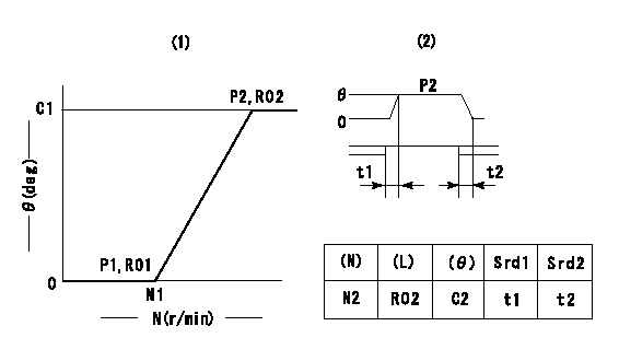
Governor adjustment

(1)Adjusting range
(2)Step response time
(N): Speed of the pump
(L): Load
(theta) Advance angle
(Srd1) Step response time 1
(Srd2) Step response time 2
1. Adjusting conditions for the variable timer
(1)Adjust the clearance between the pickup and the protrusion to L.
----------
L=1-0.2mm N2=800r/min C2=(10)deg t1=2.5--sec. t2=2.5--sec.
----------
N1=750++r/min P1=0kPa(0kgf/cm2) P2=392kPa(4kgf/cm2) C1=10+-0.3deg R01=0/4load R02=4/4load
----------
L=1-0.2mm N2=800r/min C2=(10)deg t1=2.5--sec. t2=2.5--sec.
----------
N1=750++r/min P1=0kPa(0kgf/cm2) P2=392kPa(4kgf/cm2) C1=10+-0.3deg R01=0/4load R02=4/4load
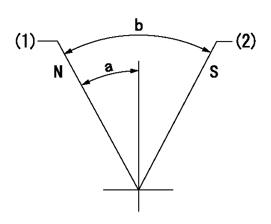
Speed control lever angle

N:Pump normal
S:Stop the pump.
(1)Rack position = aa
(2)Rack position bb
----------
aa=16mm bb=1mm
----------
a=17deg+-5deg b=27deg+-5deg
----------
aa=16mm bb=1mm
----------
a=17deg+-5deg b=27deg+-5deg
0000000901

(1)Pump vertical direction
(2)Coupling's key groove position at No 1 cylinder's beginning of injection
(3)B.T.D.C.: aa
(4)-
----------
aa=4deg
----------
a=(50deg)
----------
aa=4deg
----------
a=(50deg)
Stop lever angle

(Rs) rack sensor specifications
(C/U) control unit part number
(V) Rack sensor output voltage
(R) Rack position (mm)
1. Confirming governor output characteristics (rack 15 mm, span 6 mm)
(1)When the output voltages of the rack sensor are V1 and V2, check that the rack positions R1 and R2 in the table above are satisfied.
----------
----------
----------
----------
0000001201 RACK SENSOR

(VR) measurement voltage
(I) Part number of the control unit
(G) Apply red paint.
(H): End surface of the pump
1. Rack sensor adjustment (154610-0620)
(1)At governor side rack sensor output voltage V1, adjust the bobbin (A) so that the drive side rack sensor output voltage is VR+-0.01.
(2)Apply G at two places.
Connecting part between the joint (B) and the nut (F)
Connecting part between the joint (B) and the end surface of the pump (H)
----------
V1=1V
----------
----------
V1=1V
----------
Information:
Lubricant Viscosity Recommendations
The proper SAE grade of oil to select is determined by the minimum outside temperature at which the engine will be started and the maximum outside temperature in which the engine will be operating. This recommendation is to ensure the correct viscosity is used until the next oil change. Engine start-up at lower than specified ambient temperature requires caution. Start-up at very low ambient temperatures may require a jacket water heater, auxiliary oil heaters or other methods to increase the engine crankcase and surrounding temperatures. When operating below -20°C (-4°F) refer to Caterpillar for information.The use of multi-viscosity oils is preferred because of full protection through a wider temperature range. See chart for recommended viscosity and temperature range. To determine if the oil in the crankcase will flow in cold weather, remove the oil dipstick before starting. If the oil will flow off, the oil is fluid enough to circulate properly.Lubricant Viscosity Chart
Refill Capacities
Engine Crankcase Oil Capacity
The crankcase refill capacities reflect the engine crankcase capacity plus on-engine oil filter change. If equipped with an auxiliary oil filter system, consult the oil filter system manufacturer for information.Total Cooling System Capacity
The Total Cooling System capacity will vary, depending on the engine model (3114 or 3116), radiator system size and capacity provided by truck/vehicle manufacturer. In order to properly maintain the cooling system, Total Cooling System capacity must be known. The chart below is left blank and should be filled in by the customer to determine the Total Cooling System Capacity for his engine and application.Add 0.25 liter (0.5 U.S. pint) of Caterpillar liquid supplemental coolant additive (Conditioner) for every 30 liter (8 U.S. gallon) of cooling system capacity to maintain the cooling system at Every 250 Service Hours.