Information injection-pump assembly
ZEXEL
106873-7050
1068737050
Rating:
Cross reference number
ZEXEL
106873-7050
1068737050
Zexel num
Bosch num
Firm num
Name
106873-7050
INJECTION-PUMP ASSEMBLY
Calibration Data:
Adjustment conditions
Test oil
1404 Test oil ISO4113 or {SAEJ967d}
1404 Test oil ISO4113 or {SAEJ967d}
Test oil temperature
degC
40
40
45
Nozzle and nozzle holder
105780-8140
Bosch type code
EF8511/9A
Nozzle
105780-0000
Bosch type code
DN12SD12T
Nozzle holder
105780-2080
Bosch type code
EF8511/9
Opening pressure
MPa
17.2
Opening pressure
kgf/cm2
175
Injection pipe
Outer diameter - inner diameter - length (mm) mm 8-3-600
Outer diameter - inner diameter - length (mm) mm 8-3-600
Overflow valve
131425-0220
Overflow valve opening pressure
kPa
157
123
191
Overflow valve opening pressure
kgf/cm2
1.6
1.25
1.95
Tester oil delivery pressure
kPa
157
157
157
Tester oil delivery pressure
kgf/cm2
1.6
1.6
1.6
Direction of rotation (viewed from drive side)
Right R
Right R
Injection timing adjustment
Direction of rotation (viewed from drive side)
Right R
Right R
Injection order
1-2-7-3-
4-5-6-8
Pre-stroke
mm
3.9
3.85
3.95
Beginning of injection position
Governor side NO.1
Governor side NO.1
Difference between angles 1
Cyl.1-2 deg. 45 44.5 45.5
Cyl.1-2 deg. 45 44.5 45.5
Difference between angles 2
Cal 1-7 deg. 90 89.5 90.5
Cal 1-7 deg. 90 89.5 90.5
Difference between angles 3
Cal 1-3 deg. 135 134.5 135.5
Cal 1-3 deg. 135 134.5 135.5
Difference between angles 4
Cal 1-4 deg. 180 179.5 180.5
Cal 1-4 deg. 180 179.5 180.5
Difference between angles 5
Cal 1-5 deg. 225 224.5 225.5
Cal 1-5 deg. 225 224.5 225.5
Difference between angles 6
Cal 1-6 deg. 270 269.5 270.5
Cal 1-6 deg. 270 269.5 270.5
Difference between angles 7
Cal 1-8 deg. 315 314.5 315.5
Cal 1-8 deg. 315 314.5 315.5
Injection quantity adjustment
Adjusting point
-
Rack position
12.2
Pump speed
r/min
700
700
700
Each cylinder's injection qty
mm3/st.
109
105.7
112.3
Basic
*
Fixing the rack
*
Standard for adjustment of the maximum variation between cylinders
*
Injection quantity adjustment_02
Adjusting point
Z
Rack position
8.5+-0.5
Pump speed
r/min
510
510
510
Each cylinder's injection qty
mm3/st.
16
13.6
18.4
Fixing the rack
*
Standard for adjustment of the maximum variation between cylinders
*
Injection quantity adjustment_03
Adjusting point
A
Rack position
R1(12.2)
Pump speed
r/min
700
700
700
Average injection quantity
mm3/st.
109
108
110
Basic
*
Fixing the lever
*
Injection quantity adjustment_04
Adjusting point
B
Rack position
R1+1.15
Pump speed
r/min
1100
1100
1100
Average injection quantity
mm3/st.
118
114
122
Fixing the lever
*
Injection quantity adjustment_05
Adjusting point
C
Rack position
(R1-0.8)
Pump speed
r/min
500
500
500
Average injection quantity
mm3/st.
104
100
108
Fixing the lever
*
Test data Ex:
Governor adjustment
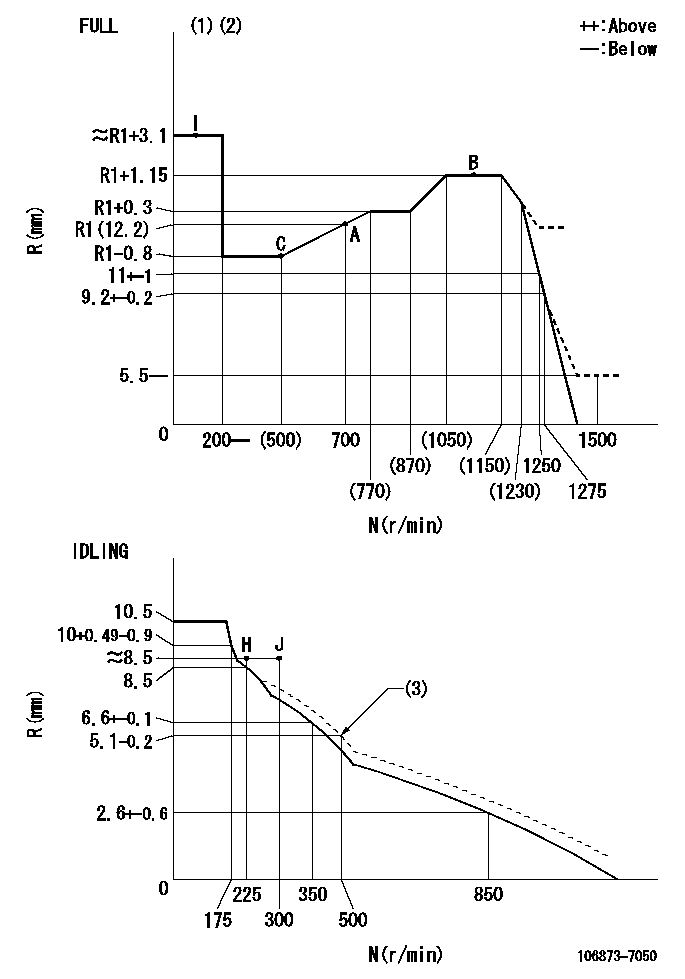
N:Pump speed
R:Rack position (mm)
(1)Torque cam stamping: T1
(2)Tolerance for racks not indicated: +-0.05mm.
(3)Damper spring setting
----------
T1=AB22
----------
----------
T1=AB22
----------
Timer adjustment

(1)Adjusting range
(2)Step response time
(N): Speed of the pump
(L): Load
(theta) Advance angle
(Srd1) Step response time 1
(Srd2) Step response time 2
1. Adjusting conditions for the variable timer
(1)Adjust the clearance between the pickup and the protrusion to L.
----------
L=1-0.2mm N2=800r/min C2=(10)deg t1=2.5--sec. t2=2.5--sec.
----------
N1=750++r/min P1=0kPa(0kgf/cm2) P2=392kPa(4kgf/cm2) C1=10+-0.3deg R01=0/4load R02=4/4load
----------
L=1-0.2mm N2=800r/min C2=(10)deg t1=2.5--sec. t2=2.5--sec.
----------
N1=750++r/min P1=0kPa(0kgf/cm2) P2=392kPa(4kgf/cm2) C1=10+-0.3deg R01=0/4load R02=4/4load
Speed control lever angle

F:Full speed
I:Idle
(1)Use the hole at R = aa
(2)Stopper bolt set position 'H'
----------
aa=30mm
----------
a=37deg+-5deg b=(44deg)+-3deg
----------
aa=30mm
----------
a=37deg+-5deg b=(44deg)+-3deg
Stop lever angle
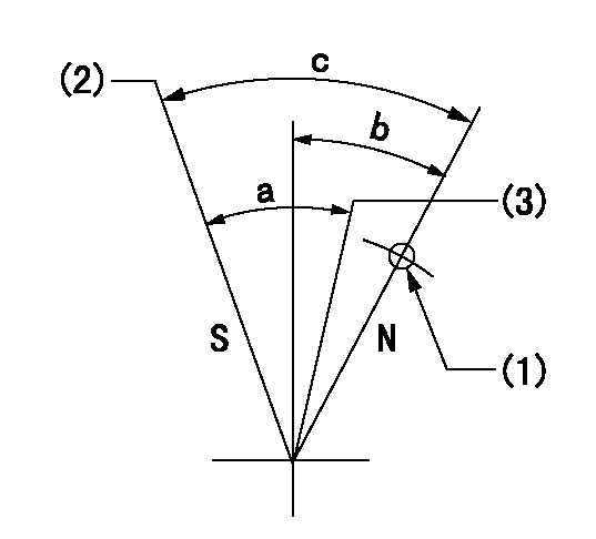
N:Pump normal
S:Stop the pump.
(1)Use the hole at R = aa
(2)Set the stopper bolt so that speed = bb and rack position = cc. (Confirm non-injection.)
(3)Normal engine position (Rack position corresponding to dd)
----------
aa=45mm bb=1100r/min cc=3.5+-0.3mm dd=18mm
----------
a=(31deg)+-5deg b=25.5deg+-5deg c=41deg+-5deg
----------
aa=45mm bb=1100r/min cc=3.5+-0.3mm dd=18mm
----------
a=(31deg)+-5deg b=25.5deg+-5deg c=41deg+-5deg
0000001501 RACK SENSOR

(VR) measurement voltage
(I) Part number of the control unit
(G) Apply red paint.
(H): End surface of the pump
1. Rack sensor adjustment (-0620)
(1)Fix the speed control lever at the full position
(2)Set the speed to N1 r/min.
(If the boost compensator is provided, apply boost pressure.)
(3)Adjust the bobbin (A) so that the rack sensor's output voltage is VR+-0.01.
(4)At that time, rack position must be Ra.
(5)Apply G at two places.
Connecting part between the joint (B) and the nut (F)
Connecting part between the joint (B) and the end surface of the pump (H)
----------
N1=1100r/min Ra=R1(12.2)+1.15mm
----------
----------
N1=1100r/min Ra=R1(12.2)+1.15mm
----------
0000001601 MICRO SWITCH
Adjustment of the micro-switch
Adjust the bolt to obtain the following lever position when the micro-switch is ON.
(1)Speed N1
(2)Rack position Ra
----------
N1=325r/min Ra=8.5+-0.1mm
----------
----------
N1=325r/min Ra=8.5+-0.1mm
----------
Timing setting

(1)Pump vertical direction
(2)Coupling's key groove position at No 1 cylinder's beginning of injection
(3)B.T.D.C.: aa
(4)-
----------
aa=4deg
----------
a=(50deg)
----------
aa=4deg
----------
a=(50deg)
Information:
3114 ATAAC Engine Model Views
Oil Filter (1), Fan Pulley & Bearing Assembly (2), Thermostat Housing (3), Alternator (4), Turbocharger (5), Electric Starting Motor (6), Crankshaft Pulley (7), Water Pump (8), Oil Level Gage (Dipstick) (9), Oil Drain Plug (10), Fuel Transfer Pump and Governor (11), Air Compressor (12), Oil Filler (13), Fuel Filter (14), Air Cleaner with Restriction Gauge (15), Lift Eye (16), Fuel Priming Pump (17), Crankcase Breather (18) and Power Steering Pump (19).3116 ATAAC Engine Model Views
LEFT SIDE VIEW
Fan Pulley & Bearing Assembly (1), Thermostat Housing (2), Crankshaft Vibration Damper & Pulley (3116 ONLY) (3), Oil Level Gage (Dipstick) (4), Oil Drain Plug (5), Fuel Transfer Pump and Governor (6), Air Compressor (7), Oil Filler (8), Fuel Filter (9), Lift Eye (10), Fuel Priming Pump (11), Crankcase Breather (12) and Power Steering Pump (13), Fuel Filter Bleed Screw (14).Engine Information
The engines described in this Manual are the 3114 and 3116 ATAAC Diesel Truck engines designed primarily for on-highway medium duty applications.3114 Engine
The Caterpillar 3114 Truck (Vehicular) Engine has a 4.4 liter (269 inch3) displacement, with 105 mm (4.13 inch) bore and 127 mm (5.0 inch) stroke. The engine is a four stroke cycle, in-line 4 cylinder with direct injection. 3116 Engine
The Caterpillar 3116 Truck (Vehicular) Engine has a 6.6 liter (403 inch3) displacement, with 105 mm (4.13 inch) bore and 127 mm (5.0 inch) stroke. The engine is a four stroke cycle, in-line 6 cylinder with direct injection. All Engines
3114 & 3116 Cylinder and Valve Location Rated speed for the Truck (Vehicular) Engine, turbocharged with Air-to-Air Aftercooling System (ATAAC), equipped with a mechanical governor and high pressure injection fuel system is 2600 rpm. Refer to the Information Plate or Caterpillar for information regarding your engine.The cooling system consists of a belt driven centrifugal pump, with a thermostat which regulates engine coolant temperature, electric fan clutch, an oil cooler and a radiator incorporating a shunt system.The engine lubricating oil (both cooled and filtered) is supplied by a gear-type pump and bypass valves provide unrestricted flow of oil to engine parts when oil viscosity is high, or if the oil cooler or filter elements become plugged.To obtain maximum efficiency and lowest cost to operate and own your Caterpillar engine, use only recommended fuels and lubricants and follow the maintenance recommendations in the Maintenance Schedule which can be found in the Maintenance Section of this Manual.Serial Number Plate and Information Plate Locations
Engine Identification
Caterpillar engines are identified with Serial Numbers, Performance Specification Numbers (fuel system settings) and Arrangement Numbers. In some cases Modification Numbers are also used. These numbers are shown on the Serial Number Plate (1) mounted on the engine.Caterpillar needs all of these numbers to determine which components were included on the engine when it was assembled at the factory. This permits accurate identification of replacement part numbers.Serial Number Plate
There are two possible locations for the Serial Number Plate (1).Some engines have the plate on the left side of the engine and some engines will have the
Have questions with 106873-7050?
Group cross 106873-7050 ZEXEL
Mitsubishi
Mitsubishi
Mitsubishi
106873-7050
INJECTION-PUMP ASSEMBLY