Information injection-pump assembly
BOSCH
F 019 Z10 132
f019z10132
ZEXEL
106873-7030
1068737030
Rating:
Service parts 106873-7030 INJECTION-PUMP ASSEMBLY:
1.
_
7.
COUPLING PLATE
8.
_
9.
_
11.
Nozzle and Holder
ME091276
12.
Open Pre:MPa(Kqf/cm2)
17.7{180}/21.6{220}
15.
NOZZLE SET
Include in #1:
106873-7030
as INJECTION-PUMP ASSEMBLY
Cross reference number
BOSCH
F 019 Z10 132
f019z10132
ZEXEL
106873-7030
1068737030
Zexel num
Bosch num
Firm num
Name
Calibration Data:
Adjustment conditions
Test oil
1404 Test oil ISO4113 or {SAEJ967d}
1404 Test oil ISO4113 or {SAEJ967d}
Test oil temperature
degC
40
40
45
Nozzle and nozzle holder
105780-8140
Bosch type code
EF8511/9A
Nozzle
105780-0000
Bosch type code
DN12SD12T
Nozzle holder
105780-2080
Bosch type code
EF8511/9
Opening pressure
MPa
17.2
Opening pressure
kgf/cm2
175
Injection pipe
Outer diameter - inner diameter - length (mm) mm 8-3-600
Outer diameter - inner diameter - length (mm) mm 8-3-600
Overflow valve
134424-1320
Overflow valve opening pressure
kPa
157
123
191
Overflow valve opening pressure
kgf/cm2
1.6
1.25
1.95
Tester oil delivery pressure
kPa
157
157
157
Tester oil delivery pressure
kgf/cm2
1.6
1.6
1.6
Direction of rotation (viewed from drive side)
Right R
Right R
Injection timing adjustment
Direction of rotation (viewed from drive side)
Right R
Right R
Injection order
1-2-7-3-
4-5-6-8
Pre-stroke
mm
4.8
4.75
4.85
Beginning of injection position
Governor side NO.1
Governor side NO.1
Difference between angles 1
Cyl.1-2 deg. 45 44.5 45.5
Cyl.1-2 deg. 45 44.5 45.5
Difference between angles 2
Cal 1-7 deg. 90 89.5 90.5
Cal 1-7 deg. 90 89.5 90.5
Difference between angles 3
Cal 1-3 deg. 135 134.5 135.5
Cal 1-3 deg. 135 134.5 135.5
Difference between angles 4
Cal 1-4 deg. 180 179.5 180.5
Cal 1-4 deg. 180 179.5 180.5
Difference between angles 5
Cal 1-5 deg. 225 224.5 225.5
Cal 1-5 deg. 225 224.5 225.5
Difference between angles 6
Cal 1-6 deg. 270 269.5 270.5
Cal 1-6 deg. 270 269.5 270.5
Difference between angles 7
Cal 1-8 deg. 315 314.5 315.5
Cal 1-8 deg. 315 314.5 315.5
Injection quantity adjustment
Adjusting point
-
Rack position
10.6
Pump speed
r/min
650
650
650
Each cylinder's injection qty
mm3/st.
129.5
125.6
133.4
Basic
*
Fixing the rack
*
Standard for adjustment of the maximum variation between cylinders
*
Injection quantity adjustment_02
Adjusting point
C
Rack position
6.2+-0.5
Pump speed
r/min
250
250
250
Each cylinder's injection qty
mm3/st.
17.5
14.9
20.1
Fixing the rack
*
Standard for adjustment of the maximum variation between cylinders
*
Injection quantity adjustment_03
Adjusting point
A
Rack position
R1(10.6)
Pump speed
r/min
650
650
650
Average injection quantity
mm3/st.
129.5
128.5
130.5
Basic
*
Fixing the lever
*
Injection quantity adjustment_04
Adjusting point
B
Rack position
R1-0.05
Pump speed
r/min
1100
1100
1100
Average injection quantity
mm3/st.
133.5
129.5
137.5
Fixing the lever
*
Injection quantity adjustment_05
Adjusting point
E
Rack position
-
Pump speed
r/min
100
100
100
Average injection quantity
mm3/st.
135
95
175
Fixing the lever
*
Remarks
After startup boost setting
After startup boost setting
Timer adjustment
Pump speed
r/min
900--
Advance angle
deg.
0
0
0
Remarks
Start
Start
Timer adjustment_02
Pump speed
r/min
850
Advance angle
deg.
0.5
Timer adjustment_03
Pump speed
r/min
1100
Advance angle
deg.
4.5
4
5
Remarks
Finish
Finish
Test data Ex:
Governor adjustment
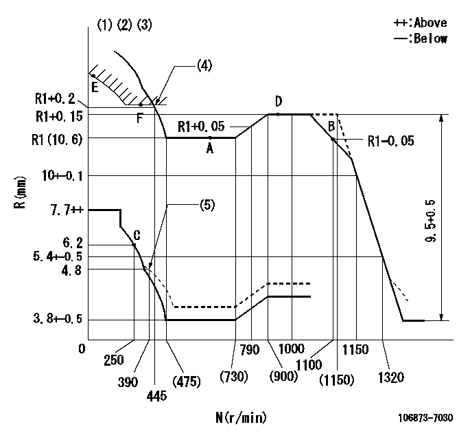
N:Pump speed
R:Rack position (mm)
(1)Lever ratio: RT
(2)Target shim dimension: TH
(3)Tolerance for racks not indicated: +-0.05mm.
(4)Excess fuel setting for starting: SXL
(5)Damper spring setting
----------
RT=0.8 TH=1.8mm SXL=(R1+1.2)+-0.1mm
----------
----------
RT=0.8 TH=1.8mm SXL=(R1+1.2)+-0.1mm
----------
Speed control lever angle
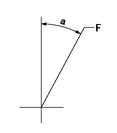
F:Full speed
----------
----------
a=(22.5deg)+-5deg
----------
----------
a=(22.5deg)+-5deg
0000000901

F:Full load
I:Idle
(1)Stopper bolt setting
----------
----------
a=10deg+-5deg b=37.5deg+-3deg
----------
----------
a=10deg+-5deg b=37.5deg+-3deg
Stop lever angle
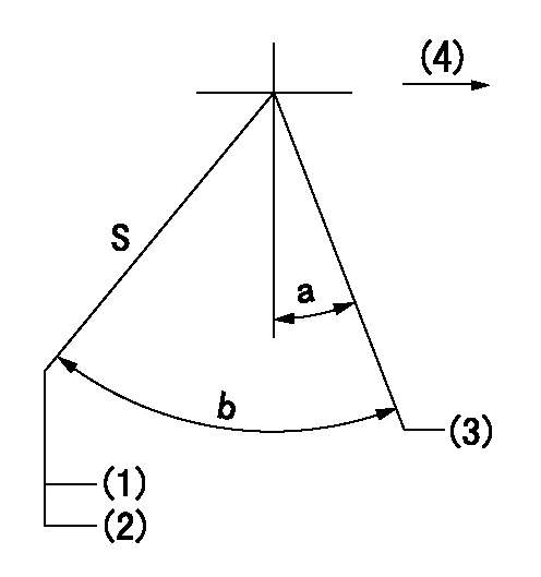
S:Stop the pump.
(1)Rack position = aa
(2)Stopper bolt setting
(3)Free (at delivery)
(4)Drive side
----------
aa=4.1-0.5mm
----------
a=10.5deg+-5deg b=55.5deg+7deg-5deg
----------
aa=4.1-0.5mm
----------
a=10.5deg+-5deg b=55.5deg+7deg-5deg
0000001501 MICRO SWITCH
Adjustment of the micro-switch
Adjust the bolt to obtain the following lever position when the micro-switch is ON.
(1)Speed N1
(2)Rack position Ra
----------
N1=325r/min Ra=5.6+-0.1mm
----------
----------
N1=325r/min Ra=5.6+-0.1mm
----------
Timing setting

(1)Pump vertical direction
(2)Coupling's key groove position at No 1 cylinder's beginning of injection
(3)B.T.D.C.: aa
(4)-
----------
aa=12deg
----------
a=(40deg)
----------
aa=12deg
----------
a=(40deg)
Information:
Caterpillar Reference Material
Oil
SEBD0640 Oil and Your EngineSEBU6310 EMA Engine Oil Data BookPEDP7105 Scheduled Oil SamplingPEDP7122 Question & Answer BookletPEHP0002 Cat Molybdenum Grease (MPGM)PEHP0003 Cat Lithium Grease (MPGL)PEHP0017 Cat Special Purpose Grease (SPG)PEHP1020 Cat Diesel Engine Oil (CF-4) Data Sheet (North America)PEHP1026 Cat Diesel Engine Oil (CF-4) Data Sheet (International)PEHP6001 How to Take a Good Oil SamplePEWP9733 Cat Fluids SelectorFuel
SEBD0717 Diesel Fuels and Your EngineSEHS7067 Fuels for Caterpillar Diesel EnginesLEKQ3363 Caterpillar Engine Data Sheet 60.1(Fuels Recommended For Use In Caterpillar Truck Engines)Coolant
SEBD0518 Know Your Cooling SystemSEBD0970 Coolant and Your EngineService Manauls
SEBR0514 Low Emission SystemSENR5105 3176 ATAAC Truck Engine Service Manual (7LG1 and Up)SENR5111 3176 ATAAC Truck Engine Schematic Manual (7LG1 and Up)SENR5112 3176 ATAAC Truck Engine Electrical Manual (7LG1 and Up)SENR5110 3176 ATAAC Truck Engine Troubleshooting Manual (7LG1 and Up)SENR5113 3176 ATAAC Truck Engine Mechanical Manual (7LG1 and Up)SENR5114 3176 ATAAC Truck Engine Performance Specifications (7LG1 and Up)SENR5115 3176 ATAAC Truck Engine OEM Systems Manual (7LG1 and Up)SENR5116 3176 ATAAC Truck Engine Jacobs Brake Manual (7LG1 and Up)Parts Manuals
SEBP1954 3176 ATAAC Truck Engine Parts Manual (7LG1 and Up)Special Instructions
SEHS8622 Using the FT1984 Air-To-Air Aftercooler Leak Test GroupSEHS9031 Storage Procedure for Caterpillar ProductsSEHS8884 Unit Injector Test SpecificationsSEHS8746 Using the 1U5540 Tool GroupSEHS8867 Using the 1U6661 Pop (Injector) Tester The following Special Instructions pertain to the operation, maintenance, diagnostic tooling and programming of the 3176 system. Some of these publications will be included in the tool kits, the others will be available thru your Caterpillar dealer.SEHS8741 Using 8C5919 Service Program Module Operating ManualSEHS8743 Using 7X1830 Service Program Module Operating ManualMiscellaneous
SEBF8029 Index to Guidelines for Reusable Parts and Salvage OperationsSEBF8062 Guideline for Reusable Parts - Cleaning and Inspection of Air FiltersSELF5052 Emission Related Components WarrantyLEDT5092 Driving Techniques For Maximum Fuel EconomyLEBT8121 Truck Engine Application and Installation GuideLEGT5087 Truck Engine Application and Installation GuideLEDT4211 PAR DirectoryLEKT8467 Specing for Peak PerformanceAll of the above publications are available through your Caterpillar dealer.Additional Reference Material
ASTM D217-68 - Worked PenetrationASTM D2896 - TBN MeasurementsASTM D2982BASTM D3828AASTM D445ASTM D893ASTM 4985-89 - GM-6038M SpecificationASTM D1384 -Glassware Corrosion TestASTM D2809 -Cavitation Corrosion of Aluminum TestASTM D4340 -Hot Surface Corrosion of Aluminum TestASTM Specs can normally be obtained from your local technological society, library or college.SAE J313 - Diesel FuelsSAE J754 - NomenclatureSAE J183 - ClassificationSAE Specs can be found in your SAE handbook or can be obtained from your local library, college or technological society.* SAE handbooks can be obtained directly from:SAE International
400 Commonwealth Drive
Warrendale, PA USA 15096-0001
All of the above publications are available through your Caterpillar dealer.SAE J313 - Diesel FuelsSAE J754 - NomenclatureSAE J183 - ClassificationSAE Specs can be found in your SAE handbook or can be obtained from your local library, college or technological society.* SAE handbooks can be obtained directly from:SAE International
400 Commonwealth Drive
Warrendale, PA USA 15096-0001
All of the above publications are available through your Caterpillar dealer.
