Information injection-pump assembly
ZEXEL
106873-3690
1068733690
HINO
220401200A
220401200a
Rating:
Cross reference number
ZEXEL
106873-3690
1068733690
HINO
220401200A
220401200a
Zexel num
Bosch num
Firm num
Name
Calibration Data:
Adjustment conditions
Test oil
1404 Test oil ISO4113 or {SAEJ967d}
1404 Test oil ISO4113 or {SAEJ967d}
Test oil temperature
degC
40
40
45
Nozzle and nozzle holder
105780-8250
Bosch type code
1 688 901 101
Nozzle
105780-0120
Bosch type code
1 688 901 990
Nozzle holder
105780-2190
Opening pressure
MPa
20.7
Opening pressure
kgf/cm2
211
Injection pipe
Outer diameter - inner diameter - length (mm) mm 8-3-600
Outer diameter - inner diameter - length (mm) mm 8-3-600
Overflow valve
134424-4120
Overflow valve opening pressure
kPa
255
221
289
Overflow valve opening pressure
kgf/cm2
2.6
2.25
2.95
Tester oil delivery pressure
kPa
255
255
255
Tester oil delivery pressure
kgf/cm2
2.6
2.6
2.6
Direction of rotation (viewed from drive side)
Right R
Right R
Injection timing adjustment
Direction of rotation (viewed from drive side)
Right R
Right R
Injection order
1-8-6-2-
7-5-4-3
Pre-stroke
mm
4.2
4.14
4.2
Beginning of injection position
Drive side NO.1
Drive side NO.1
Difference between angles 1
Cal 1-8 deg. 45 44.75 45.25
Cal 1-8 deg. 45 44.75 45.25
Difference between angles 2
Cal 1-6 deg. 90 89.75 90.25
Cal 1-6 deg. 90 89.75 90.25
Difference between angles 3
Cyl.1-2 deg. 135 134.75 135.25
Cyl.1-2 deg. 135 134.75 135.25
Difference between angles 4
Cal 1-7 deg. 180 179.75 180.25
Cal 1-7 deg. 180 179.75 180.25
Difference between angles 5
Cal 1-5 deg. 225 224.75 225.25
Cal 1-5 deg. 225 224.75 225.25
Difference between angles 6
Cal 1-4 deg. 270 269.75 270.25
Cal 1-4 deg. 270 269.75 270.25
Difference between angles 7
Cal 1-3 deg. 315 314.75 315.25
Cal 1-3 deg. 315 314.75 315.25
Injection quantity adjustment
Adjusting point
-
Rack position
12.3
Pump speed
r/min
700
700
700
Average injection quantity
mm3/st.
131
128
134
Max. variation between cylinders
%
0
-3
3
Basic
*
Fixing the rack
*
Standard for adjustment of the maximum variation between cylinders
*
Injection quantity adjustment_02
Adjusting point
Z
Rack position
8+-0.5
Pump speed
r/min
460
460
460
Average injection quantity
mm3/st.
13.3
12.3
14.3
Max. variation between cylinders
%
0
-10
10
Fixing the rack
*
Standard for adjustment of the maximum variation between cylinders
*
Injection quantity adjustment_03
Adjusting point
A
Rack position
R1(12.3)
Pump speed
r/min
700
700
700
Average injection quantity
mm3/st.
131
129
133
Basic
*
Fixing the lever
*
Injection quantity adjustment_04
Adjusting point
B
Rack position
R1+0.5
Pump speed
r/min
1100
1100
1100
Average injection quantity
mm3/st.
121.5
115.5
127.5
Fixing the lever
*
Timer adjustment
Pump speed
r/min
760--
Advance angle
deg.
0
0
0
Remarks
Start
Start
Timer adjustment_02
Pump speed
r/min
710
Advance angle
deg.
0.3
Timer adjustment_03
Pump speed
r/min
(770)
Advance angle
deg.
2.25
1.95
2.55
Remarks
Measure the actual speed.
Measure the actual speed.
Timer adjustment_04
Pump speed
r/min
(900)
Advance angle
deg.
2.25
1.95
2.55
Remarks
Measure the actual speed.
Measure the actual speed.
Timer adjustment_05
Pump speed
r/min
1050+50
Advance angle
deg.
6.75
6.45
7.05
Remarks
Finish
Finish
Test data Ex:
Governor adjustment
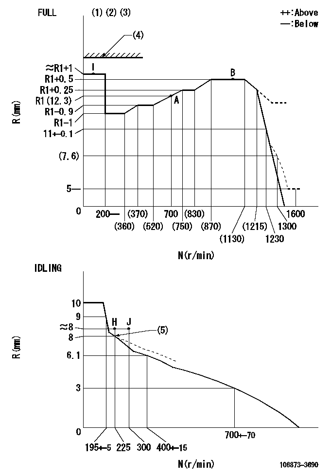
N:Pump speed
R:Rack position (mm)
(1)Torque cam stamping: T1
(2)Tolerance for racks not indicated: +-0.05mm.
(3)Set stop lever before governor adjustment. [When setting stop lever after governor adjustment, confirm that point I (Ra) can be obtained at full setting.]
(4)Stop lever's normal position setting: equivalent to RA
(5)Damper spring setting: DL
----------
T1=AF07 Ra=R1+1mm RA=17.5mm DL=7.9-0.1mm
----------
----------
T1=AF07 Ra=R1+1mm RA=17.5mm DL=7.9-0.1mm
----------
Speed control lever angle

F:Full speed
I:Idle
(1)Use the hole at R = aa
(2)Stopper bolt set position 'H'
----------
aa=94mm
----------
a=17deg+-5deg b=(41.5deg)+-3deg
----------
aa=94mm
----------
a=17deg+-5deg b=(41.5deg)+-3deg
Stop lever angle
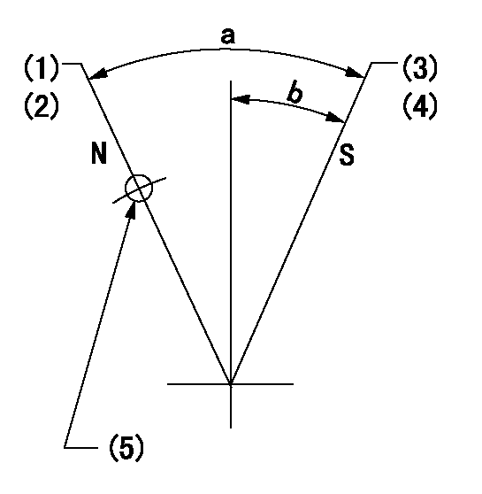
N:Pump normal
S:Stop the pump.
(1)Rack position = aa
(2)Set the stopper screw. (After setting, apply red paint.)
(3)Rack position = bb (speed = cc)
(4)Set the stopper screw. (After setting, apply red paint.)
(5)Use the hole above R = dd
----------
aa=(17.5)mm bb=1+-0.3mm cc=0r/min dd=35mm
----------
a=35deg+-5deg b=29.5deg+-5deg
----------
aa=(17.5)mm bb=1+-0.3mm cc=0r/min dd=35mm
----------
a=35deg+-5deg b=29.5deg+-5deg
Timing setting

(1)Pump vertical direction
(2)Coupling's key groove position at No 1 cylinder's beginning of injection
(3)-
(4)-
----------
----------
a=(80deg)
----------
----------
a=(80deg)
Information:
Under the Hood Inspection
For maximum service life of your truck engine, make a thorough under the hood inspection before starting the engine. Look for such items as oil or coolant leaks, loose bolts, worn belts and trash build-up. Remove trash build-up and have repairs made as needed.Perform required Daily maintenance before starting the engine.
Each time any significant quantity of oil (or other fluid) is spilled on or near the engine it should be cleaned up. Accumulated grease and oil on an engine is a fire hazard. Remove this debris with steam cleaning or high pressure water at PM Level 2 or every 6000 hours.Wipe clean all fittings, caps and plugs before servicing.
Starting the Engine
Do not store starting fluid containers in the cab. Failure to do so, could result in an explosion and/or fire and possible personal injury.If equipped with an electrically or fuel ignited manifold heater, DO NOT use ether.
Startability will be improved at temperatures below +32°F (0°C) by the use of a starting aid (ether) or use of a cylinder block coolant heater or other means to heat the crankcase oil. This will help alleviate white smoke and misfire during cold weather start-up.Use ether when temperatures are below 32°F (0°C) for cold weather starting purposes only.
When using starting fluid, follow the manufacturer's instructions carefully, use it sparingly and spray it ONLY WHILE CRANKING THE ENGINE. Excessive ether can cause piston and ring damage.Use ether for cold starting purposes only.
If the engine fails to start within 30 seconds, release the starter switch and wait two minutes to allow the starter motor to cool before using it again.Start the engine using the following procedure:1. Place the transmission in NEUTRAL and disengage the flywheel clutch (if equipped) to remove the transmission drag and prevent movement of the truck.Depressing the clutch in cold weather can mean the difference between starting and not starting. Depressing the clutch in warm weather produces faster starts and reduces battery drain.2. Turn the ignition switch to the ON position and push the crank button or turn the ignition switch to the START position.3. Crank the engine. If the engine fails to start in 30 seconds, release the starting (ignition) switch and wait two minutes to allow the starter motor to cool before using it again.
Do not increase engine speed until the oil pressure gauge indicates normal. Oil pressure should raise within 15 seconds after the engine starts.If oil pressure is not indicated on gauge within 15 seconds, do not drive the truck. Stop the engine, investigate and correct the cause.
4. Allow the engine to idle three to five minutes, or until the water temperature gauge has begun to rise. Check all gauges during the warm-up period.5. Check fuel level gauge. Do not fill fuel tank to top. Fuel expands as it gets warm and may overflow.Starting With Jumper Cables
When boost starting an engine, follow the instructions to properly start the engine. This engine may be equipped with a 12 or 24 volt starting system. Use only