Information injection-pump assembly
ZEXEL
106873-3620
1068733620

Rating:
Service parts 106873-3620 INJECTION-PUMP ASSEMBLY:
1.
_
7.
COUPLING PLATE
8.
_
9.
_
11.
Nozzle and Holder
23600-3020A
12.
Open Pre:MPa(Kqf/cm2)
14.7{150}/21.6{220}
14.
NOZZLE
Include in #1:
106873-3620
as INJECTION-PUMP ASSEMBLY
Cross reference number
ZEXEL
106873-3620
1068733620
Zexel num
Bosch num
Firm num
Name
106873-3620
INJECTION-PUMP ASSEMBLY
Calibration Data:
Adjustment conditions
Test oil
1404 Test oil ISO4113 or {SAEJ967d}
1404 Test oil ISO4113 or {SAEJ967d}
Test oil temperature
degC
40
40
45
Nozzle and nozzle holder
105780-8250
Bosch type code
1 688 901 101
Nozzle
105780-0120
Bosch type code
1 688 901 990
Nozzle holder
105780-2190
Opening pressure
MPa
20.7
Opening pressure
kgf/cm2
211
Injection pipe
Outer diameter - inner diameter - length (mm) mm 8-3-600
Outer diameter - inner diameter - length (mm) mm 8-3-600
Overflow valve
134424-4120
Overflow valve opening pressure
kPa
255
221
289
Overflow valve opening pressure
kgf/cm2
2.6
2.25
2.95
Tester oil delivery pressure
kPa
255
255
255
Tester oil delivery pressure
kgf/cm2
2.6
2.6
2.6
Direction of rotation (viewed from drive side)
Right R
Right R
Injection timing adjustment
Direction of rotation (viewed from drive side)
Right R
Right R
Injection order
1-8-6-2-
7-5-4-3
Pre-stroke
mm
4.2
4.14
4.2
Beginning of injection position
Drive side NO.1
Drive side NO.1
Difference between angles 1
Cal 1-8 deg. 45 44.75 45.25
Cal 1-8 deg. 45 44.75 45.25
Difference between angles 2
Cal 1-6 deg. 90 89.75 90.25
Cal 1-6 deg. 90 89.75 90.25
Difference between angles 3
Cyl.1-2 deg. 135 134.75 135.25
Cyl.1-2 deg. 135 134.75 135.25
Difference between angles 4
Cal 1-7 deg. 180 179.75 180.25
Cal 1-7 deg. 180 179.75 180.25
Difference between angles 5
Cal 1-5 deg. 225 224.75 225.25
Cal 1-5 deg. 225 224.75 225.25
Difference between angles 6
Cal 1-4 deg. 270 269.75 270.25
Cal 1-4 deg. 270 269.75 270.25
Difference between angles 7
Cal 1-3 deg. 315 314.75 315.25
Cal 1-3 deg. 315 314.75 315.25
Injection quantity adjustment
Adjusting point
-
Rack position
12.3
Pump speed
r/min
700
700
700
Average injection quantity
mm3/st.
131
128
134
Max. variation between cylinders
%
0
-3
3
Basic
*
Fixing the rack
*
Standard for adjustment of the maximum variation between cylinders
*
Injection quantity adjustment_02
Adjusting point
Z
Rack position
8+-0.5
Pump speed
r/min
460
460
460
Average injection quantity
mm3/st.
13.3
12.3
14.3
Max. variation between cylinders
%
0
-10
10
Fixing the rack
*
Standard for adjustment of the maximum variation between cylinders
*
Injection quantity adjustment_03
Adjusting point
A
Rack position
R1(12.3)
Pump speed
r/min
700
700
700
Average injection quantity
mm3/st.
131
129
133
Basic
*
Fixing the lever
*
Injection quantity adjustment_04
Adjusting point
B
Rack position
R1+0.5
Pump speed
r/min
1100
1100
1100
Average injection quantity
mm3/st.
121.5
115.5
127.5
Fixing the lever
*
Timer adjustment
Pump speed
r/min
760--
Advance angle
deg.
0
0
0
Remarks
Start
Start
Timer adjustment_02
Pump speed
r/min
710
Advance angle
deg.
0.3
Timer adjustment_03
Pump speed
r/min
(770)
Advance angle
deg.
2.25
1.95
2.55
Remarks
Measure the actual speed.
Measure the actual speed.
Timer adjustment_04
Pump speed
r/min
(900)
Advance angle
deg.
2.25
1.95
2.55
Remarks
Measure the actual speed.
Measure the actual speed.
Timer adjustment_05
Pump speed
r/min
1050+50
Advance angle
deg.
6.75
6.45
7.05
Remarks
Finish
Finish
Test data Ex:
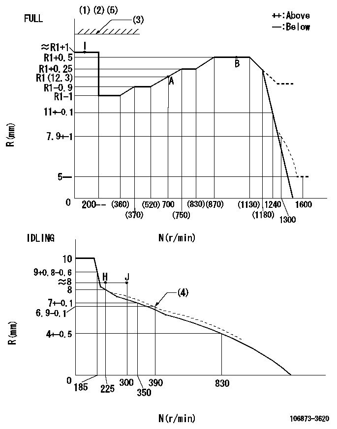
Governor adjustment

N:Pump speed
R:Rack position (mm)
(1)Torque cam stamping: T1
(2)Tolerance for racks not indicated: +-0.05mm.
(3)Stop lever's normal position setting: equivalent to R2
(4)Damper spring setting
(5)Set the stop lever before governor adjustment. [When setting the stop lever after governor adjustment, confirm that R = R1 + 1 (point I) can be obtained at the full setting.]
----------
T1=AD48 R2=17.5mm
----------
----------
T1=AD48 R2=17.5mm
----------
Speed control lever angle

F:Full speed
I:Idle
(1)Use the hole at R = aa
(2)Stopper bolt set position 'H'
----------
aa=94mm
----------
a=17deg+-5deg b=39deg+-3deg
----------
aa=94mm
----------
a=17deg+-5deg b=39deg+-3deg
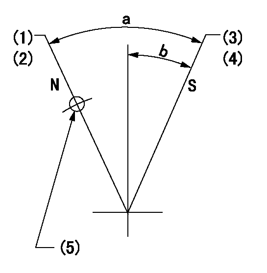
Stop lever angle

N:Pump normal
S:Stop the pump.
(1)Rack position = aa
(2)Set the stopper screw. (After setting, apply red paint.)
(3)Rack position = bb (speed = cc)
(4)Set the stopper screw. (After setting, apply red paint.)
(5)Use the hole above R = dd
----------
aa=(17.5)mm bb=1+-0.3mm cc=0r/min dd=35mm
----------
a=35deg+-5deg b=29.5deg+-5deg
----------
aa=(17.5)mm bb=1+-0.3mm cc=0r/min dd=35mm
----------
a=35deg+-5deg b=29.5deg+-5deg
Timing setting

(1)Pump vertical direction
(2)Coupling's key groove position at No 1 cylinder's beginning of injection
(3)-
(4)-
----------
----------
a=(80deg)
----------
----------
a=(80deg)
Information:
Customer Assistance
When a problem arises concerning the sale, operation or service of your engine, it will normally be handled by the distributor or dealer in your area. Please refer to the Caterpillar Truck Engine Parts & Service Directory which will identify the facility nearest you, the hours of operation, phone number and how to locate the dealer.Caterpillar has authorized parts & service outlets throughout North America to satisfy your needs. These authorized dealers provide:* Factory Trained Service Personnel.* At many locations, 24 hour a day service and parts availability.* Complete offering of Remanufactured Components.* Product information and published service literature.Your satisfaction is a primary concern to Caterpillar, its distributors and their dealers. To assure your complete satisfaction, we suggest the following steps be followed should you have a problem that has not been handled to your satisfaction.Step One
Discuss your problem with a member of management from the distributorship or dealership. If your problem originates with a dealer, explain the matter to a management member of the distributorship with whom the dealer has his parts and service agreement.Step Two
When it appears that your problem cannot be readily resolved at the distributor level without additional assistance, contact your Caterpillar District Office. The phone number is available at the dealer/distributor.Step Three
If you are still not satisfied, call Caterpillar Factory Customer Services (24 hour service) at 1 (800) 447-4986.When contacting Caterpillar direct, please keep in mind that ultimately your problem will likely be resolved at the distributorship/dealership using their facilities, equipment and personnel. Therefore, it is suggested that you follow the above steps in sequence when experiencing a problem.
Have questions with 106873-3620?
Group cross 106873-3620 ZEXEL
Hino
106873-3620
INJECTION-PUMP ASSEMBLY