Information injection-pump assembly
ZEXEL
106873-3610
1068733610
HINO
220009850A
220009850a

Rating:
Service parts 106873-3610 INJECTION-PUMP ASSEMBLY:
1.
_
7.
COUPLING PLATE
8.
_
9.
_
11.
Nozzle and Holder
23600-3040A
12.
Open Pre:MPa(Kqf/cm2)
14.7{150}/21.6{220}
14.
NOZZLE
Include in #1:
106873-3610
as INJECTION-PUMP ASSEMBLY
Cross reference number
ZEXEL
106873-3610
1068733610
HINO
220009850A
220009850a
Zexel num
Bosch num
Firm num
Name
Calibration Data:
Adjustment conditions
Test oil
1404 Test oil ISO4113 or {SAEJ967d}
1404 Test oil ISO4113 or {SAEJ967d}
Test oil temperature
degC
40
40
45
Nozzle and nozzle holder
105780-8250
Bosch type code
1 688 901 101
Nozzle
105780-0120
Bosch type code
1 688 901 990
Nozzle holder
105780-2190
Opening pressure
MPa
20.7
Opening pressure
kgf/cm2
211
Injection pipe
Outer diameter - inner diameter - length (mm) mm 8-3-600
Outer diameter - inner diameter - length (mm) mm 8-3-600
Overflow valve
134424-4120
Overflow valve opening pressure
kPa
255
221
289
Overflow valve opening pressure
kgf/cm2
2.6
2.25
2.95
Tester oil delivery pressure
kPa
255
255
255
Tester oil delivery pressure
kgf/cm2
2.6
2.6
2.6
Direction of rotation (viewed from drive side)
Right R
Right R
Injection timing adjustment
Direction of rotation (viewed from drive side)
Right R
Right R
Injection order
1-8-6-2-
7-5-4-3
Pre-stroke
mm
4
3.94
4
Beginning of injection position
Drive side NO.1
Drive side NO.1
Difference between angles 1
Cal 1-8 deg. 45 44.75 45.25
Cal 1-8 deg. 45 44.75 45.25
Difference between angles 2
Cal 1-6 deg. 90 89.75 90.25
Cal 1-6 deg. 90 89.75 90.25
Difference between angles 3
Cyl.1-2 deg. 135 134.75 135.25
Cyl.1-2 deg. 135 134.75 135.25
Difference between angles 4
Cal 1-7 deg. 180 179.75 180.25
Cal 1-7 deg. 180 179.75 180.25
Difference between angles 5
Cal 1-5 deg. 225 224.75 225.25
Cal 1-5 deg. 225 224.75 225.25
Difference between angles 6
Cal 1-4 deg. 270 269.75 270.25
Cal 1-4 deg. 270 269.75 270.25
Difference between angles 7
Cal 1-3 deg. 315 314.75 315.25
Cal 1-3 deg. 315 314.75 315.25
Injection quantity adjustment
Adjusting point
-
Rack position
12.9
Pump speed
r/min
700
700
700
Average injection quantity
mm3/st.
140.5
137.5
143.5
Max. variation between cylinders
%
0
-3
3
Basic
*
Fixing the rack
*
Standard for adjustment of the maximum variation between cylinders
*
Injection quantity adjustment_02
Adjusting point
Z
Rack position
8.3+-0.5
Pump speed
r/min
420
420
420
Average injection quantity
mm3/st.
15.9
14.9
16.9
Max. variation between cylinders
%
0
-10
10
Fixing the rack
*
Standard for adjustment of the maximum variation between cylinders
*
Injection quantity adjustment_03
Adjusting point
A
Rack position
R1(12.9)
Pump speed
r/min
700
700
700
Average injection quantity
mm3/st.
140.5
138.5
142.5
Basic
*
Fixing the lever
*
Injection quantity adjustment_04
Adjusting point
B
Rack position
R1+0.35
Pump speed
r/min
1100
1100
1100
Average injection quantity
mm3/st.
127
121
133
Fixing the lever
*
Injection quantity adjustment_05
Adjusting point
C
Rack position
R1-1.05
Pump speed
r/min
330
330
330
Average injection quantity
mm3/st.
138
128
148
Fixing the lever
*
Timer adjustment
Pump speed
r/min
710--
Advance angle
deg.
0
0
0
Load
2/5
Remarks
Start
Start
Timer adjustment_02
Pump speed
r/min
660
Advance angle
deg.
0.3
Load
2/5
Timer adjustment_03
Pump speed
r/min
(760)
Advance angle
deg.
2
1.7
2.3
Load
2/5
Remarks
Measure the actual speed.
Measure the actual speed.
Timer adjustment_04
Pump speed
r/min
900+50
Advance angle
deg.
2
1.7
2.3
Load
4/5
Timer adjustment_05
Pump speed
r/min
1100-50
Advance angle
deg.
5.75
5.45
6.05
Load
5/5
Remarks
Finish
Finish
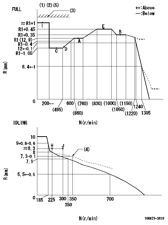
Test data Ex:
Governor adjustment

N:Pump speed
R:Rack position (mm)
(1)Torque cam stamping: T1
(2)Tolerance for racks not indicated: +-0.05mm.
(3)Stop lever's normal position setting: equivalent to R2
(4)Damper spring setting
(5)Set the stop lever before governor adjustment. [When setting the stop lever after governor adjustment, confirm that R = R1 + 1 (point I) can be obtained at the full setting.]
----------
T1=AD70 R2=17.5mm
----------
----------
T1=AD70 R2=17.5mm
----------
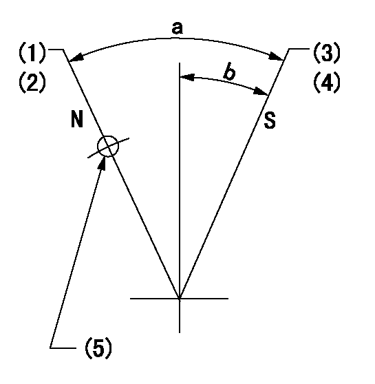
Speed control lever angle

F:Full speed
I:Idle
(1)Use the hole at R = aa
(2)Stopper bolt set position 'H'
----------
aa=94mm
----------
a=15deg+-5deg b=42.5deg+-3deg
----------
aa=94mm
----------
a=15deg+-5deg b=42.5deg+-3deg
Stop lever angle

N:Pump normal
S:Stop the pump.
(1)Rack position = aa
(2)Set the stopper screw. (After setting, apply red paint.)
(3)Rack position = bb (speed = cc)
(4)Set the stopper screw. (After setting, apply red paint.)
(5)Use the hole above R = dd
----------
aa=(17.5)mm bb=1.5+-0.3mm cc=0r/min dd=35mm
----------
a=35deg+-5deg b=15deg+-5deg
----------
aa=(17.5)mm bb=1.5+-0.3mm cc=0r/min dd=35mm
----------
a=35deg+-5deg b=15deg+-5deg
Timing setting

(1)Pump vertical direction
(2)Coupling's key groove position at No 1 cylinder's beginning of injection
(3)-
(4)-
----------
----------
a=(80deg)
----------
----------
a=(80deg)
Information:
Caterpillar Reference Material
Oil
SEBD0640 Oil and Your EngineSEBU6310 EMA Engine Oil Data BookPEDP7105 Scheduled Oil SamplingPEDP7122 Question & Answer BookletPEHP0002 Cat Molybdenum Grease (MPGM)PEHP0003 Cat Lithium Grease (MPGL)PEHP0017 Cat Special Purpose Grease (SPG)PEHP1020 Cat Diesel Engine Oil (CF-4) Data Sheet (North America)PEHP1026 Cat Diesel Engine Oil (CF-4) Data Sheet (International)PEHP6001 How to Take a Good Oil SamplePEWP9733 Cat Fluids SelectorFuel
SEBD0717 Diesel Fuels and Your EngineSEHS7067 Fuels for Caterpillar Diesel EnginesLEKQ3363 Caterpillar Engine Data Sheet 60.1 (Fuels Recommended For Use In Caterpillar Truck Engines)Coolant
SEBD0518 Know Your Cooling SystemSEBD0970 Coolant and Your EngineService Manuals
SEBR0514 Low Emission SystemSEBR0560 3406C (Mechanical) Service Manual (3ZJ16182 and Up, 5KJ07800 and Up)SENR5505 3406C (Electronic) Service Manual (4CK00846 and Up)Special Instructions
The following Special Instructions pertain to the operation, maintenance, diagnostic tooling and programming of the PEEC system. Some of these publications will be included in the tool kits, the others will be available thru your Caterpillar dealer.SEHS7808 Using the 6V3060 Low Emission System TesterSEHS8622 Using the FT1984 Air-To-Air Aftercooler Leak Test GroupSEHS8627 and SEHS9083 Using the 1U5540 Tool GroupSEHS8741 Using the 8C5919 Service Program ModuleSEHS8742 Using the 8T8697 Electronic Control Analyzer Programmer (ECAP)SEHS8743 Using the 8C4629 Digital Diagnostic Tool (DDT) with Programmable Electronic Engine Control ModuleSEHS8746 Using the 1U5540 Tool GroupSEHS8807 Programmable Electronic Engine Control Screen Map(s)SEHS9031 Storage Procedure for Caterpillar ProductsSEHS9349 Using the 8C5919 Service Program ModuleMiscellaneous
LEBT8121 Truck Engine Application and Installation Guide (4-88)LEDT4211 PAR DirectoryLEDT5092 Driving Techniques For Maximum Fuel EconomyLEGT5087 Truck Engine Application and Installation GuideLEHQ6101 General Instructions and Application GuideLEKT8467 Specing for Peak PerformanceLEXT7056 Performance Analysis Report (PAR) Testing for 3406 Electronic Truck EnginesPEDP0026 Power Analysis ReportSEBD0794 3400 Engine-Major Component Performance GuideSEBF8029 Index to Guidelines for Reusable Parts and Salvage OperationsSEBF8062 Guideline for Reusable Parts (Cleaning and Inspection of Air Filters)SELF5052 Emission Related Components WarrantyAdditional Reference Material
ASTM D217-68 - Worked PenetrationASTM D2896 - TBN MeasurementsASTM D2982BASTM D3828AASTM D445ASTM D893ASTM 4985-89 - GM-6038M SpecificationASTM Specs can normally be obtained from your local technological society, library or college.SAE J313 - Diesel FuelsSAE J754 - NomenclatureSAE J183 - ClassificationSAE Specs can be found in your SAE handbook or can be obtained from your local library, college or technological society.* SAE handbooks can be obtained directly from:SAE International
400 Commonwealth Drive
Warrendale, PA USA 15096-0001
All of the above publications are available through your Caterpillar dealer.Customer Specified Reference Numbers
Below is space for information on the programmed specifications to be filled in by the owner. ENGINE: 3406 Electronic* VEHICLE IDENTIFICATION NO. (VIN)____________________* RATING SELECTION NUMBER____________________* CUSTOMER PASSWORDS: Password No. 1 ____________________Password No. 2 ____________________* VEHICLE SPEED PARAMETERS: Vehicle Speed Calibration____________________ppmTachometer Calibration____________________pprVehicle Speed Limit (VSL)____________________mph (km/h)5 mph Vehicle Speed Droop ____________________Engine RPM @ VSL____________________rpm* CRUISE CONTROL (CC) PARAMETERS: Low Cruise Control Speed Set Limit (LCC)____________________mph (km/h)High Cruise Control Speed Set Limit (HCC)____________________mph (km/h)Engine Retarder Mode ____________________Cruise Switch Configuration ____________________* PTO GOVERNOR PARAMETERS: PTO Mode Speed Limit____________________mph (km/h)PTO Mode Engine Speed (rpm) Limit____________________rpmPTO Engine Speed Ramp Rate____________________rpm/sec.* PROGRESSIVE SHIFTING PARAMETERS: Low Gears #1 (LoGr#1) Engine RPM Limit____________________rpmLow Gears #1 (LoGr#1)