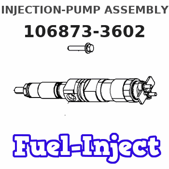
Information injection-pump assembly
BOSCH
9 400 618 446
9400618446
ZEXEL
106873-3602
1068733602
HINO
220009711A
220009711a
Rating:
Cross reference number
BOSCH
9 400 618 446
9400618446
ZEXEL
106873-3602
1068733602
HINO
220009711A
220009711a
Zexel num
Bosch num
Firm num
Name
Calibration Data:
Adjustment conditions
Test oil
1404 Test oil ISO4113 or {SAEJ967d}
1404 Test oil ISO4113 or {SAEJ967d}
Test oil temperature
degC
40
40
45
Nozzle and nozzle holder
105780-8140
Bosch type code
EF8511/9A
Nozzle
105780-0000
Bosch type code
DN12SD12T
Nozzle holder
105780-2080
Bosch type code
EF8511/9
Opening pressure
MPa
17.2
Opening pressure
kgf/cm2
175
Injection pipe
Outer diameter - inner diameter - length (mm) mm 8-3-600
Outer diameter - inner diameter - length (mm) mm 8-3-600
Overflow valve
131425-0020
Overflow valve opening pressure
kPa
127
107
147
Overflow valve opening pressure
kgf/cm2
1.3
1.1
1.5
Tester oil delivery pressure
kPa
157
157
157
Tester oil delivery pressure
kgf/cm2
1.6
1.6
1.6
Direction of rotation (viewed from drive side)
Right R
Right R
Injection timing adjustment
Direction of rotation (viewed from drive side)
Right R
Right R
Injection order
1-8-6-2-
7-5-4-3
Pre-stroke
mm
4.2
4.14
4.2
Beginning of injection position
Drive side NO.1
Drive side NO.1
Difference between angles 1
Cal 1-8 deg. 45 44.75 45.25
Cal 1-8 deg. 45 44.75 45.25
Difference between angles 2
Cal 1-6 deg. 90 89.75 90.25
Cal 1-6 deg. 90 89.75 90.25
Difference between angles 3
Cyl.1-2 deg. 135 134.75 135.25
Cyl.1-2 deg. 135 134.75 135.25
Difference between angles 4
Cal 1-7 deg. 180 179.75 180.25
Cal 1-7 deg. 180 179.75 180.25
Difference between angles 5
Cal 1-5 deg. 225 224.75 225.25
Cal 1-5 deg. 225 224.75 225.25
Difference between angles 6
Cal 1-4 deg. 270 269.75 270.25
Cal 1-4 deg. 270 269.75 270.25
Difference between angles 7
Cal 1-3 deg. 315 314.75 315.25
Cal 1-3 deg. 315 314.75 315.25
Injection quantity adjustment
Adjusting point
A
Rack position
8
Pump speed
r/min
700
700
700
Average injection quantity
mm3/st.
143.5
141.5
145.5
Max. variation between cylinders
%
0
-3
3
Basic
*
Fixing the lever
*
Injection quantity adjustment_02
Adjusting point
B
Rack position
7.9
Pump speed
r/min
500
500
500
Average injection quantity
mm3/st.
140
137
143
Fixing the lever
*
Injection quantity adjustment_03
Adjusting point
D
Rack position
8.05
Pump speed
r/min
1100
1100
1100
Average injection quantity
mm3/st.
136.5
132.5
140.5
Fixing the lever
*
Injection quantity adjustment_04
Adjusting point
E
Rack position
7.6
Pump speed
r/min
1200
1200
1200
Average injection quantity
mm3/st.
122.5
117.5
127.5
Fixing the lever
*
Injection quantity adjustment_05
Adjusting point
F
Rack position
3.4+-0.5
Pump speed
r/min
225
225
225
Average injection quantity
mm3/st.
12
9
15
Max. variation between cylinders
%
0
-10
10
Fixing the rack
*
Injection quantity adjustment_06
Adjusting point
G
Rack position
8.35+-0.
1
Pump speed
r/min
330
330
330
Average injection quantity
mm3/st.
149.5
143.5
155.5
Fixing the lever
*
Remarks
Startup boost setting
Startup boost setting
Injection quantity adjustment_07
Adjusting point
H
Rack position
-
Pump speed
r/min
100
100
100
Average injection quantity
mm3/st.
170
170
190
Fixing the lever
*
Remarks
After startup boost setting
After startup boost setting
Timer adjustment
Pump speed
r/min
570--
Advance angle
deg.
0
0
0
Load
0/5
Remarks
Start
Start
Timer adjustment_02
Pump speed
r/min
520
Advance angle
deg.
0.3
Load
0/5
Timer adjustment_03
Pump speed
r/min
(550)
Advance angle
deg.
2
1.7
2.3
Load
0/5
Remarks
Measure the actual speed.
Measure the actual speed.
Timer adjustment_04
Pump speed
r/min
900+50
Advance angle
deg.
2
1.7
2.3
Load
4/5
Timer adjustment_05
Pump speed
r/min
1100-50
Advance angle
deg.
6.75
6.45
7.05
Load
5/5
Remarks
Finish
Finish
Test data Ex:
Governor adjustment
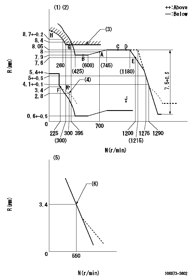
N:Pump speed
R:Rack position (mm)
(1)Tolerance for racks not indicated: +-0.05mm.
(2)Set idle at point K (N = N1, R = R1) and confirm that the injection quantity does not exceed Q1 at point J (N = N2).
(3)Excess fuel setting for starting: SXL
(4)Damper spring setting
(5)Variable speed specification: idling adjustment
(6)Main spring setting
----------
N1=300r/min R1=3.4mm N2=1100r/min Q1=3mm3/st SXL=8.35+-0.1mm
----------
----------
N1=300r/min R1=3.4mm N2=1100r/min Q1=3mm3/st SXL=8.35+-0.1mm
----------
Speed control lever angle
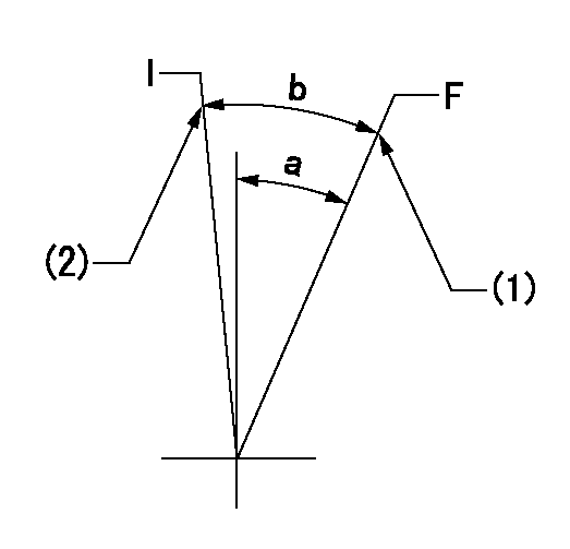
F:Full speed
I:Idle
(1)Stopper bolt setting
(2)Stopper bolt setting
----------
----------
a=14.5deg+-5deg b=(15.5deg)+-5deg
----------
----------
a=14.5deg+-5deg b=(15.5deg)+-5deg
0000000901

F:Full load
I:Idle
(1)Use the hole at R = aa
(2)Stopper bolt setting
----------
aa=39mm
----------
a=39deg+-5deg b=39.5deg+-3deg
----------
aa=39mm
----------
a=39deg+-5deg b=39.5deg+-3deg
Stop lever angle
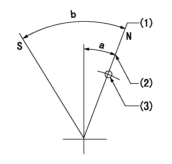
N:Pump normal
S:Stop the pump.
(1)Rack position = aa (set before setting excess fuel for starting)
(2)Set the stopper bolt (apply red paint).
(3)Use the hole at R = bb
----------
aa=12+0.5mm bb=37mm
----------
a=17.5deg+-5deg b=35deg+-5deg
----------
aa=12+0.5mm bb=37mm
----------
a=17.5deg+-5deg b=35deg+-5deg
Timing setting

(1)Pump vertical direction
(2)Coupling's key groove position at No 1 cylinder's beginning of injection
(3)-
(4)-
----------
----------
a=(80deg)
----------
----------
a=(80deg)
Information:
Maintenance Recommendations
Caterpillar Inc. truck engines are certified by the United States Environmental Protection Agency (EPA) to comply with smoke and gaseous emission standards prescribed by Federal laws at the time of manufacture.Efficiency of emission control and engine performance depends on adherence to proper operation and maintenance recommendations AND use of recommended fuels and lubricating oils. It is recommended that major adjustments and repair be made by your authorized Caterpillar dealer.Various chemical fuel additives claiming to reduce visible smoke are available commercially. Although additives have been used by individuals to solve some isolated smoke problems in the field, they are not recommended for general use. Federal smoke regulations require that engines be certified without smoke depressants.The corrective steps taken immediately on discovery of worn parts, which may affect emission levels, will help assure proper operation of emission control systems. The use of genuine Caterpillar parts is recommended. Suppliers of non-Caterpillar parts must assure the owner that the use of such parts will not adversely affect emission levels.Regular maintenance intervals, along with special emphasis on the following items, are necessary to keep exhaust emissions within acceptable limits for the useful life of the engine. Refer to the Maintenance Section of this manual. If the engine is operating under severe conditions, adjust the maintenance schedule accordingly. See your authorized Caterpillar dealer to help analyze your specific application, operating environment and maintenance schedule adjustments.The following is an explanation of maintenance for emission-related components. See the Maintenance Schedule for the specific interval for the following items. FUEL INJECTION NOZZLES - Fuel nozzles are subject to tip wear as a result of fuel contamination. This damage can cause an increase in fuel consumption, the engine to emit black smoke, misfire or run rough. Inspect and replace if necessary. Fuel nozzles can be tested by an authorized Caterpillar truck engine dealer. TURBOCHARGER - Check for any unusual sound or vibration in the turbocharger. Inspect inlet and exhaust piping and connections. Check bearing condition and perform maintenance as described in the Maintenance Schedule. AIR/FUEL RATIO CONTROL - This component is a device to control the smoke emission of an engine during its operation when low inlet manifold pressure exists.Slow engine response and low power may indicate a need for adjustment or repair. Your Caterpillar dealer is equipped with the necessary tools, personnel and procedures to perform this service.Owner is encouraged to keep adequate maintenance records, but the absence of such, in and of itself, will not invalidate the warranty.The vehicle owner may perform routine maintenance, repairs and other non warranty work or have it done at any repair facility. Such non warranty work need not be performed at a designated warranty station in order for the warranty to remain in force.Customer Assistance-Emission Control Systems Warranty
Caterpillar Inc. aims to ensure that the Emission Control Systems warranty is properly administered. In the event that you do not receive the warranty service to which you believe you are entitled under the Emission Control Systems Warranty, call or write:Caterpillar Inc.
Manager,