Information injection-pump assembly
BOSCH
9 400 618 443
9400618443
ZEXEL
106873-3571
1068733571
HINO
220009840A
220009840a
Rating:
Service parts 106873-3571 INJECTION-PUMP ASSEMBLY:
1.
_
7.
COUPLING PLATE
8.
_
9.
_
11.
Nozzle and Holder
23600-3030A
12.
Open Pre:MPa(Kqf/cm2)
14.7{150}/24.5{250}
14.
NOZZLE
Include in #1:
106873-3571
as INJECTION-PUMP ASSEMBLY
Cross reference number
BOSCH
9 400 618 443
9400618443
ZEXEL
106873-3571
1068733571
HINO
220009840A
220009840a
Zexel num
Bosch num
Firm num
Name
106873-3571
9 400 618 443
220009840A HINO
INJECTION-PUMP ASSEMBLY
YJ41 K 14CD INJECTION PUMP ASSY PE8P PE
YJ41 K 14CD INJECTION PUMP ASSY PE8P PE
Calibration Data:
Adjustment conditions
Test oil
1404 Test oil ISO4113 or {SAEJ967d}
1404 Test oil ISO4113 or {SAEJ967d}
Test oil temperature
degC
40
40
45
Nozzle and nozzle holder
105780-8140
Bosch type code
EF8511/9A
Nozzle
105780-0000
Bosch type code
DN12SD12T
Nozzle holder
105780-2080
Bosch type code
EF8511/9
Opening pressure
MPa
17.2
Opening pressure
kgf/cm2
175
Injection pipe
Outer diameter - inner diameter - length (mm) mm 8-3-600
Outer diameter - inner diameter - length (mm) mm 8-3-600
Overflow valve
131425-0020
Overflow valve opening pressure
kPa
127
107
147
Overflow valve opening pressure
kgf/cm2
1.3
1.1
1.5
Tester oil delivery pressure
kPa
157
157
157
Tester oil delivery pressure
kgf/cm2
1.6
1.6
1.6
Direction of rotation (viewed from drive side)
Right R
Right R
Injection timing adjustment
Direction of rotation (viewed from drive side)
Right R
Right R
Injection order
1-8-6-2-
7-5-4-3
Pre-stroke
mm
4.2
4.14
4.2
Beginning of injection position
Drive side NO.1
Drive side NO.1
Difference between angles 1
Cal 1-8 deg. 45 44.75 45.25
Cal 1-8 deg. 45 44.75 45.25
Difference between angles 2
Cal 1-6 deg. 90 89.75 90.25
Cal 1-6 deg. 90 89.75 90.25
Difference between angles 3
Cyl.1-2 deg. 135 134.75 135.25
Cyl.1-2 deg. 135 134.75 135.25
Difference between angles 4
Cal 1-7 deg. 180 179.75 180.25
Cal 1-7 deg. 180 179.75 180.25
Difference between angles 5
Cal 1-5 deg. 225 224.75 225.25
Cal 1-5 deg. 225 224.75 225.25
Difference between angles 6
Cal 1-4 deg. 270 269.75 270.25
Cal 1-4 deg. 270 269.75 270.25
Difference between angles 7
Cal 1-3 deg. 315 314.75 315.25
Cal 1-3 deg. 315 314.75 315.25
Injection quantity adjustment
Adjusting point
A
Rack position
8
Pump speed
r/min
700
700
700
Average injection quantity
mm3/st.
143.5
141.5
145.5
Max. variation between cylinders
%
0
-3
3
Basic
*
Fixing the lever
*
Injection quantity adjustment_02
Adjusting point
B
Rack position
7.9
Pump speed
r/min
500
500
500
Average injection quantity
mm3/st.
140
137
143
Fixing the lever
*
Injection quantity adjustment_03
Adjusting point
D
Rack position
8.05
Pump speed
r/min
1100
1100
1100
Average injection quantity
mm3/st.
136.5
132.5
140.5
Fixing the lever
*
Injection quantity adjustment_04
Adjusting point
E
Rack position
7.6
Pump speed
r/min
1200
1200
1200
Average injection quantity
mm3/st.
122.5
117.5
127.5
Fixing the lever
*
Injection quantity adjustment_05
Adjusting point
F
Rack position
3.4+-0.5
Pump speed
r/min
225
225
225
Average injection quantity
mm3/st.
12
11
13
Max. variation between cylinders
%
0
-10
10
Fixing the rack
*
Injection quantity adjustment_06
Adjusting point
G
Rack position
8.35+-0.
1
Pump speed
r/min
330
330
330
Average injection quantity
mm3/st.
149.5
143.5
155.5
Fixing the lever
*
Remarks
Startup boost setting
Startup boost setting
Injection quantity adjustment_07
Adjusting point
H
Rack position
-
Pump speed
r/min
100
100
100
Average injection quantity
mm3/st.
170
170
190
Fixing the lever
*
Remarks
After startup boost setting
After startup boost setting
Timer adjustment
Pump speed
r/min
570--
Advance angle
deg.
0
0
0
Load
0/5
Remarks
Start
Start
Timer adjustment_02
Pump speed
r/min
520
Advance angle
deg.
0.3
Load
0/5
Timer adjustment_03
Pump speed
r/min
(550)
Advance angle
deg.
2
1.7
2.3
Load
0/5
Remarks
Measure the actual speed.
Measure the actual speed.
Timer adjustment_04
Pump speed
r/min
900+50
Advance angle
deg.
2
1.7
2.3
Load
4/5
Timer adjustment_05
Pump speed
r/min
1100-50
Advance angle
deg.
6.75
6.45
7.05
Load
5/5
Remarks
Finish
Finish
Test data Ex:
Governor adjustment
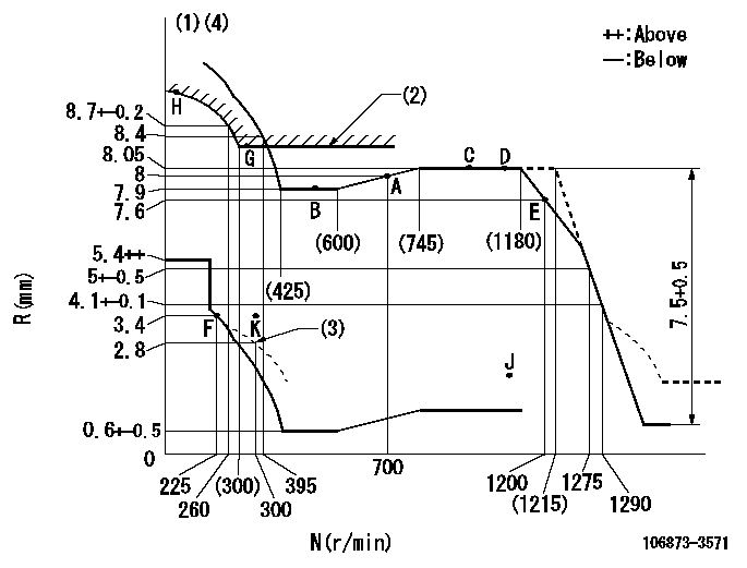
N:Pump speed
R:Rack position (mm)
(1)Tolerance for racks not indicated: +-0.05mm.
(2)Excess fuel setting for starting: SXL
(3)Damper spring setting
(4)Set idle at point K (N = N1, R = R1) and confirm that the injection quantity does not exceed Q1 at point J (N = N2).
----------
SXL=8.35+-0.1mm N1=300r/min R1=3.4mm N2=1100r/min Q1=3mm3/st
----------
----------
SXL=8.35+-0.1mm N1=300r/min R1=3.4mm N2=1100r/min Q1=3mm3/st
----------
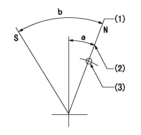
Speed control lever angle

F:Full speed
----------
----------
a=14.5deg+-5deg
----------
----------
a=14.5deg+-5deg
0000000901

F:Full load
I:Idle
(1)Use the hole at R = aa
(2)Stopper bolt setting
----------
aa=39mm
----------
a=39deg+-5deg b=39.5deg+-3deg
----------
aa=39mm
----------
a=39deg+-5deg b=39.5deg+-3deg
Stop lever angle
N:Pump normal
S:Stop the pump.
(1)Rack position = aa (set before setting excess fuel for starting)
(2)Set the stopper bolt (apply red paint).
(3)Use the hole at R = bb
----------
aa=12+0.5mm bb=37mm
----------
a=17.5deg+-5deg b=35deg+-5deg
----------
aa=12+0.5mm bb=37mm
----------
a=17.5deg+-5deg b=35deg+-5deg
Timing setting

(1)Pump vertical direction
(2)Coupling's key groove position at No 1 cylinder's beginning of injection
(3)-
(4)-
----------
----------
a=(80deg)
----------
----------
a=(80deg)
Information:
Fuel line clamps should not be over torqued. Over torqueing causes the clamps to butterfly, which results in low clamping force and fuel line vibration and eventual failure.
Tighten fuel line clamps as required using 6V4980 Torque Screwdriver Tool Group. The standard torque for these fasteners (#10 screw) is 20 lb inch (2.26 N m).* Inspect engine wiring and electronic wiring harnesses for loose connections and worn or frayed wires. Inspect:
* Air intake system hoses and elbows for cracks and loose clamps.All guards must be in place.Check condition of batteries and the level of electrolyte, unless equipped with a maintenance free battery.Refer to OEM truck owner manual or manufacturers' recommendations for battery maintenance.Engine Crankcase
Make sure you read and understand the information in the Lubricant Specifications section of this manual before you proceed with maintenance of the crankcase lube oil system.
Check Oil Level
The vehicle must be parked on a level surface to perform this maintenance procedure.
1. Check the oil level with the engine stopped.Ensure that the engine when the oil level is not above the FULL RANGE zone on the dipstick. 2. Maintain the oil level between the ADD and FULL marks in the FULL RANGE zone on the ENGINE STOPPED side of the dipstick. Do not fill the crankcase above the FULL RANGE zone. Operating your engine when the oil level is above the FULL RANGE zone could cause your crankshaft to dip into the oil. If this happens, the air bubbles created from the crankshaft dipping into the oil will reduce the lubricating characteristics of your oil and also result in the loss of power.If the dipstick does not have a FULL mark in the FULL RANGE zone, refer to Dipstick Calibration in this manual or consult your Caterpillar dealer before changing oil and operating the engine. 3. Remove the oil filler cap and add oil if necessary. See Refill Capacities and Lubricant Specifications for the size of your engine crankcase and recommended oil to use. Remote mounted filter or auxiliary filters require additional oil than what the Refill Capacities chart states. For all information pertaining to auxiliary oil filters, refer to the truck OEM or filter manufacturer's instructions.Cooling System
Make sure you read and understand the information in the Cooling System Specifications section of this manual before you proceed with maintenance of the cooling system.
Check Coolant Level
1. Check the coolant level with the engine stopped and cool.2. Remove the filler cap slowly to relieve any pressure.3. Maintain the coolant level within 1/2 inch (13 mm) below the bottom of the fill pipe or to the proper level on the sight glass, if equipped.4. Inspect the filler cap. Replace the cap if gaskets are damaged. Install the filler cap.5. Inspect and clean the radiator fins.Air Cleaner Indicator (If Equipped)
Check Air Cleaner Service Indicator
Typical air cleaner indicator shown.Your engine may be equipped with a different indicator.A service indicator (if equipped) may be mounted on your dashboard or in the engine compartment. A colored piston showing in the window indicates the
Have questions with 106873-3571?
Group cross 106873-3571 ZEXEL
Hino
Hino
Hino
Hino
106873-3571
9 400 618 443
220009840A
INJECTION-PUMP ASSEMBLY
YJ41
YJ41