Information injection-pump assembly
BOSCH
9 400 611 029
9400611029
ZEXEL
106873-3532
1068733532
HINO
220009381A
220009381a

Rating:
Service parts 106873-3532 INJECTION-PUMP ASSEMBLY:
1.
_
7.
COUPLING PLATE
8.
_
9.
_
11.
Nozzle and Holder
23600-2741B
12.
Open Pre:MPa(Kqf/cm2)
14.7{150}/24.5{250}
14.
NOZZLE
Include in #1:
106873-3532
as INJECTION-PUMP ASSEMBLY
Cross reference number
BOSCH
9 400 611 029
9400611029
ZEXEL
106873-3532
1068733532
HINO
220009381A
220009381a
Zexel num
Bosch num
Firm num
Name
Calibration Data:
Adjustment conditions
Test oil
1404 Test oil ISO4113 or {SAEJ967d}
1404 Test oil ISO4113 or {SAEJ967d}
Test oil temperature
degC
40
40
45
Nozzle and nozzle holder
105780-8140
Bosch type code
EF8511/9A
Nozzle
105780-0000
Bosch type code
DN12SD12T
Nozzle holder
105780-2080
Bosch type code
EF8511/9
Opening pressure
MPa
17.2
Opening pressure
kgf/cm2
175
Injection pipe
Outer diameter - inner diameter - length (mm) mm 8-3-600
Outer diameter - inner diameter - length (mm) mm 8-3-600
Overflow valve
131425-0020
Overflow valve opening pressure
kPa
127
107
147
Overflow valve opening pressure
kgf/cm2
1.3
1.1
1.5
Tester oil delivery pressure
kPa
157
157
157
Tester oil delivery pressure
kgf/cm2
1.6
1.6
1.6
Direction of rotation (viewed from drive side)
Right R
Right R
Injection timing adjustment
Direction of rotation (viewed from drive side)
Right R
Right R
Injection order
1-8-6-2-
7-5-4-3
Pre-stroke
mm
4.2
4.14
4.2
Beginning of injection position
Drive side NO.1
Drive side NO.1
Difference between angles 1
Cal 1-8 deg. 45 44.75 45.25
Cal 1-8 deg. 45 44.75 45.25
Difference between angles 2
Cal 1-6 deg. 90 89.75 90.25
Cal 1-6 deg. 90 89.75 90.25
Difference between angles 3
Cyl.1-2 deg. 135 134.75 135.25
Cyl.1-2 deg. 135 134.75 135.25
Difference between angles 4
Cal 1-7 deg. 180 179.75 180.25
Cal 1-7 deg. 180 179.75 180.25
Difference between angles 5
Cal 1-5 deg. 225 224.75 225.25
Cal 1-5 deg. 225 224.75 225.25
Difference between angles 6
Cal 1-4 deg. 270 269.75 270.25
Cal 1-4 deg. 270 269.75 270.25
Difference between angles 7
Cal 1-3 deg. 315 314.75 315.25
Cal 1-3 deg. 315 314.75 315.25
Injection quantity adjustment
Adjusting point
A
Rack position
8.3
Pump speed
r/min
700
700
700
Average injection quantity
mm3/st.
139.5
137.5
141.5
Max. variation between cylinders
%
0
-3
3
Basic
*
Fixing the lever
*
Injection quantity adjustment_02
Adjusting point
B
Rack position
8.2
Pump speed
r/min
500
500
500
Average injection quantity
mm3/st.
137
134
140
Fixing the lever
*
Injection quantity adjustment_03
Adjusting point
D
Rack position
8.35+-0.
5
Pump speed
r/min
1100
1100
1100
Average injection quantity
mm3/st.
132.5
124.5
140.5
Fixing the lever
*
Injection quantity adjustment_04
Adjusting point
E
Rack position
7.5
Pump speed
r/min
1200
1200
1200
Average injection quantity
mm3/st.
109.5
104.5
114.5
Fixing the lever
*
Injection quantity adjustment_05
Adjusting point
F
Rack position
3.8+-0.5
Pump speed
r/min
250
250
250
Average injection quantity
mm3/st.
12
9
15
Max. variation between cylinders
%
0
-10
10
Fixing the rack
*
Injection quantity adjustment_06
Adjusting point
G
Rack position
9+-0.1
Pump speed
r/min
330
330
330
Average injection quantity
mm3/st.
156.5
150.5
162.5
Fixing the lever
*
Remarks
Startup boost setting
Startup boost setting
Injection quantity adjustment_07
Adjusting point
H
Rack position
-
Pump speed
r/min
100
100
100
Average injection quantity
mm3/st.
160
160
200
Fixing the lever
*
Remarks
After startup boost setting
After startup boost setting
Timer adjustment
Pump speed
r/min
570--
Advance angle
deg.
0
0
0
Load
0/5
Remarks
Start
Start
Timer adjustment_02
Pump speed
r/min
520
Advance angle
deg.
0.3
Load
0/5
Timer adjustment_03
Pump speed
r/min
(550)
Advance angle
deg.
2
1.7
2.3
Load
0/5
Remarks
Measure the actual speed.
Measure the actual speed.
Timer adjustment_04
Pump speed
r/min
900+50
Advance angle
deg.
2
1.7
2.3
Load
4/5
Timer adjustment_05
Pump speed
r/min
1100-50
Advance angle
deg.
6.75
6.45
7.05
Load
5/5
Remarks
Finish
Finish
Test data Ex:
Governor adjustment
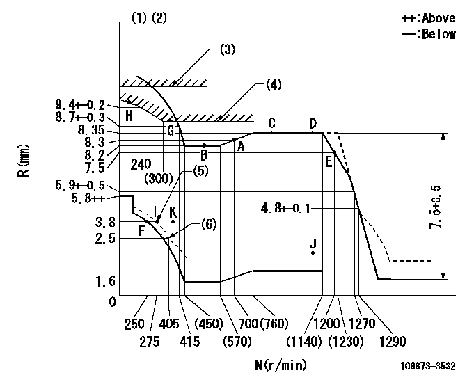
N:Pump speed
R:Rack position (mm)
(1)Tolerance for racks not indicated: +-0.05mm.
(2)Set idle at point K (N = N1, R = R1) and confirm that the injection quantity does not exceed Q1 at point J (N = N2).
(3)Stop lever's normal position setting: R2
(4)Excess fuel setting for starting: SXL
(5)When air cylinder is operating.
(6)Damper spring setting
----------
N1=300r/min R1=3.8mm N2=1100r/min Q1=3mm3/st R2=12+0.5mm SXL=9+-0.1mm
----------
----------
N1=300r/min R1=3.8mm N2=1100r/min Q1=3mm3/st R2=12+0.5mm SXL=9+-0.1mm
----------
Speed control lever angle

F:Full speed
----------
----------
a=20.5deg+-5deg
----------
----------
a=20.5deg+-5deg
0000000901
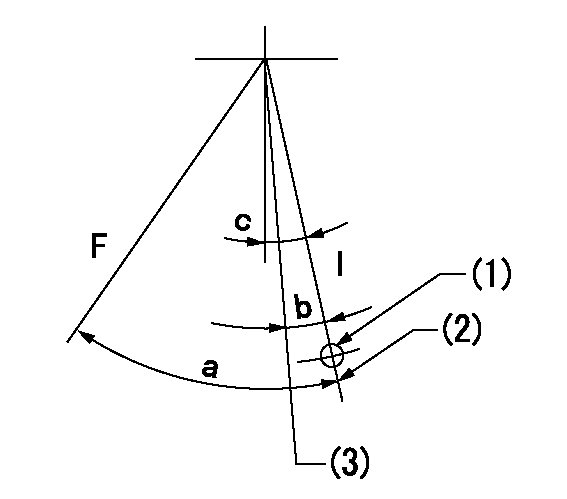
F:Full load
I:Idle
(1)Use the hole at R = aa
(2)Stopper bolt setting
(3)Set point I (at air cylinder operation)
----------
aa=90mm
----------
a=35deg+-3deg b=(1deg)+-3deg c=10deg+-5deg
----------
aa=90mm
----------
a=35deg+-3deg b=(1deg)+-3deg c=10deg+-5deg
Stop lever angle
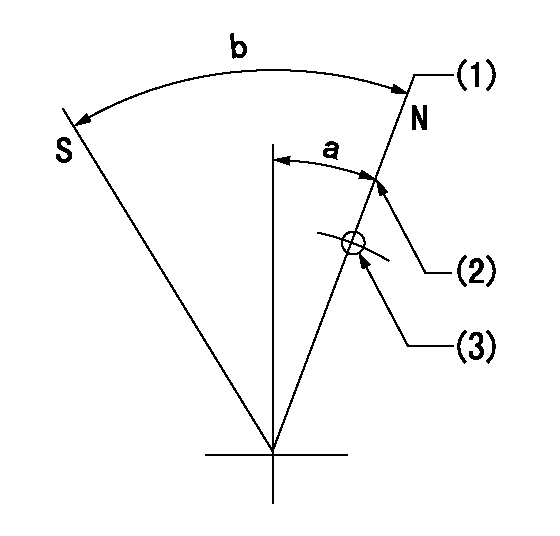
N:Pump normal
S:Stop the pump.
(1)Rack position = aa (set before setting excess fuel for starting)
(2)Set the stopper bolt (apply red paint).
(3)Use the pin at R = bb
----------
aa=12+0.5mm bb=37mm
----------
a=20deg+-5deg b=35deg+-5deg
----------
aa=12+0.5mm bb=37mm
----------
a=20deg+-5deg b=35deg+-5deg
0000001501 LEVER

1. Air cylinder adjustment
(1)With the load lever in the idle position, temporarily set the distance between the load lever A and the air cylinder D at approximately L.
(2)Set N1 and apply P1 to the air cylinder D.
(3)Adjust set bolt (D) to obtain R1 at the same speed.
(4)Lock using nut C.
(5)Apply positive pressure several times.
(6)Confirm that the load lever A returns to the idling position N2 at pressure P2.
(7)Also at P1 confirm R1 (N1).
----------
L=5mm R1=3.8mm N1=275r/min N2=250r/min P1=392+98kPa(4+1kgf/cm2) P2=0kPa(0kgf/cm2)
----------
----------
L=5mm R1=3.8mm N1=275r/min N2=250r/min P1=392+98kPa(4+1kgf/cm2) P2=0kPa(0kgf/cm2)
----------
Timing setting

(1)Pump vertical direction
(2)Coupling's key groove position at No 1 cylinder's beginning of injection
(3)-
(4)-
----------
----------
a=(80deg)
----------
----------
a=(80deg)
Information:
Lubricant Information
Certain abbreviations follow Society of Automotive Engineers (SAE) J754 nomenclature and some classifications follow SAE J183 abbreviations. The MIL specifications are U.S.A. Military Specifications. The CCMC refers to an organization of major European manufacturers responsible for defining engine oil performance specifications. The definitions other than Caterpillar's will be of assistance in purchasing lubricants. Recommended oil viscosities can be found in the Lubricant Viscosities chart in this publication.Grease is classified by the National Lubricating Grease Institute (NLGI) based on ASTM D217-68 Worked Penetration characteristics which are given a defined consistency number.A new oil performance category has been released by the American Petroleum Institute (API) for the diesel engine oil and by Caterpillar for engine oil. The new category is:* API CF-4 (engine oil)The API CF-4 has become the new category for the API CE type oils. The performance tests for this oil will be the new Cat 1K single cylinder oil test engine and other engine tests which are presently part of the CE oil evaluation.Engine Lubricant Specification
Caterpillar has an oil formulation to provide maximum performance and life for your on-highway diesel truck engine. Cat Engine Oils are offered in a full line of appropriate single and multi-viscosity grades to meet the performance and ambient temperature requirements for heavy duty diesel truck engines.Caterpillar recommends the following specifications to achieve the maximum engine life and performance with your on-highway diesel truck engine.* Caterpillar Engine Oil Cat Diesel Engine Oil-DEO (CF-4)Cat Diesel Engine Oil-DEO (CD)Cat Oils are performance rated as SAE 10W30 - API CF-4 (new category); API CE;SAE 15W40 - API CF-4 (new category); API CE;API CD-IISAE 30 - API CD-II; API CDCat Engine Oil is currently being used for factory fill for engines and is offered by Caterpillar dealers for continued refill use. Consult your Caterpillar dealer for this Cat Oil.Cat Diesel Engine Oil DEO (CF-4) is an oil formulated with strong dispersancy effectiveness along with sufficient alkalinity and low sulfated ash level for performance requirements of engine operation in today's and future designs. Oils meeting the American Petroleum Institute (API) CF-4 performance category possess the properties to operate effectively at the higher piston temperatures of some current and future engines.The DEO (CF-4) oil type to be selected will depend on the engine type, fuel sulfur, application and customer preference.The DEO (CF-4) oil is blended in viscosity grades of SAE 10W30 and 15W40. Multi-grade oils are required because of the significantly lower oil consumption of multi-viscosity oils as compared to single grades. Oil consumption and piston crownland deposits are very important in the engine tests used to evaluate oil performance. This oil is also qualified as API SG which allows its use in gasoline engine applications requiring this performance rating.Cat Diesel Engine Oil DEO (CD) is blended with a diesel engine type additive with strong detergency effectiveness. This oil has a higher alkalinity (13.5 TBN) than many oils for the neutralization of wear causing combustion products and provides additional protection for higher fuel sulfur. This oil is blended