Information injection-pump assembly
ZEXEL
106873-3103
1068733103
HINO
220007883A
220007883a

Rating:
Cross reference number
ZEXEL
106873-3103
1068733103
HINO
220007883A
220007883a
Zexel num
Bosch num
Firm num
Name
Calibration Data:
Adjustment conditions
Test oil
1404 Test oil ISO4113 or {SAEJ967d}
1404 Test oil ISO4113 or {SAEJ967d}
Test oil temperature
degC
40
40
45
Nozzle and nozzle holder
105780-8140
Bosch type code
EF8511/9A
Nozzle
105780-0000
Bosch type code
DN12SD12T
Nozzle holder
105780-2080
Bosch type code
EF8511/9
Opening pressure
MPa
17.2
Opening pressure
kgf/cm2
175
Injection pipe
Outer diameter - inner diameter - length (mm) mm 8-3-600
Outer diameter - inner diameter - length (mm) mm 8-3-600
Overflow valve
134424-0820
Overflow valve opening pressure
kPa
127
107
147
Overflow valve opening pressure
kgf/cm2
1.3
1.1
1.5
Tester oil delivery pressure
kPa
157
157
157
Tester oil delivery pressure
kgf/cm2
1.6
1.6
1.6
Direction of rotation (viewed from drive side)
Right R
Right R
Injection timing adjustment
Direction of rotation (viewed from drive side)
Right R
Right R
Injection order
1-8-6-2-
7-5-4-3
Pre-stroke
mm
4.8
4.74
4.8
Beginning of injection position
Drive side NO.1
Drive side NO.1
Difference between angles 1
Cal 1-8 deg. 45 44.75 45.25
Cal 1-8 deg. 45 44.75 45.25
Difference between angles 2
Cal 1-6 deg. 90 89.75 90.25
Cal 1-6 deg. 90 89.75 90.25
Difference between angles 3
Cyl.1-2 deg. 135 134.75 135.25
Cyl.1-2 deg. 135 134.75 135.25
Difference between angles 4
Cal 1-7 deg. 180 179.75 180.25
Cal 1-7 deg. 180 179.75 180.25
Difference between angles 5
Cal 1-5 deg. 225 224.75 225.25
Cal 1-5 deg. 225 224.75 225.25
Difference between angles 6
Cal 1-4 deg. 270 269.75 270.25
Cal 1-4 deg. 270 269.75 270.25
Difference between angles 7
Cal 1-3 deg. 315 314.75 315.25
Cal 1-3 deg. 315 314.75 315.25
Injection quantity adjustment
Adjusting point
A
Rack position
8.9
Pump speed
r/min
700
700
700
Average injection quantity
mm3/st.
139.3
137.3
141.3
Max. variation between cylinders
%
0
-2
2
Basic
*
Fixing the lever
*
Injection quantity adjustment_02
Adjusting point
B
Rack position
8.95+-0.
5
Pump speed
r/min
1100
1100
1100
Average injection quantity
mm3/st.
133.1
129.1
137.1
Fixing the lever
*
Injection quantity adjustment_03
Adjusting point
F
Rack position
3.8+-0.5
Pump speed
r/min
225
225
225
Average injection quantity
mm3/st.
10.4
7.4
13.4
Max. variation between cylinders
%
0
-15
15
Fixing the rack
*
Injection quantity adjustment_04
Adjusting point
G
Rack position
-
Pump speed
r/min
100
100
100
Average injection quantity
mm3/st.
139
139
Fixing the lever
*
Remarks
After startup boost setting
After startup boost setting
Timer adjustment
Pump speed
r/min
750--
Advance angle
deg.
0
0
0
Load
1/4
Remarks
Start
Start
Timer adjustment_02
Pump speed
r/min
700
Advance angle
deg.
0.3
Load
1/4
Timer adjustment_03
Pump speed
r/min
820--
Advance angle
deg.
0.7
0.4
1
Load
4/4
Timer adjustment_04
Pump speed
r/min
900+50
Advance angle
deg.
0.7
0.4
1
Load
3/4
Timer adjustment_05
Pump speed
r/min
1100-50
Advance angle
deg.
5.25
4.95
5.55
Load
4/4
Remarks
Finish
Finish
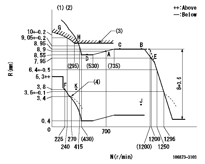
Test data Ex:
Governor adjustment

N:Pump speed
R:Rack position (mm)
(1)Tolerance for racks not indicated: +-0.05mm.
(2)Set idle at point K (N = N1, R = R1) and confirm that the injection quantity does not exceed Q1 at point J (N = N2).
(3)Excess fuel setting for starting: SXL
(4)Damper spring setting
----------
N1=325r/min R1=3.8mm N2=1100r/min Q1=3mm3/st SXL=9.45+-0.1mm
----------
----------
N1=325r/min R1=3.8mm N2=1100r/min Q1=3mm3/st SXL=9.45+-0.1mm
----------
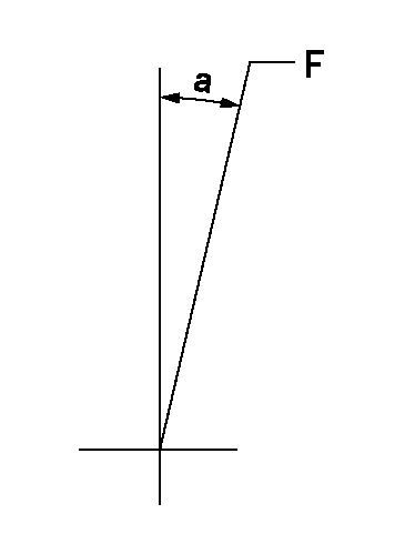
Speed control lever angle

F:Full speed
----------
----------
a=15.5deg+-5deg
----------
----------
a=15.5deg+-5deg
0000000901

F:Full load
I:Idle
(1)Use the hole at R = aa
(2)Stopper bolt setting
----------
aa=39mm
----------
a=39deg+-5deg b=43.5deg+-3deg
----------
aa=39mm
----------
a=39deg+-5deg b=43.5deg+-3deg
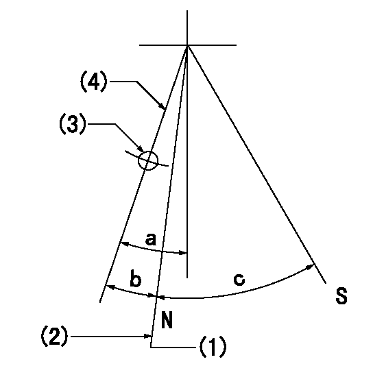
Stop lever angle

N:Pump normal
S:Stop the pump.
(1)Rack position = aa (at delivery), set before governor adjustment
(2)Set the stopper bolt (apply red paint).
(3)Use the pin at R = bb
(4)Lever free
----------
aa=12+-0.1mm bb=37mm
----------
a=(9deg)+-5deg b=9deg+-5deg c=35deg+-5deg
----------
aa=12+-0.1mm bb=37mm
----------
a=(9deg)+-5deg b=9deg+-5deg c=35deg+-5deg
Timing setting

(1)Pump vertical direction
(2)Coupling's key groove position at No 1 cylinder's beginning of injection
(3)-
(4)-
----------
----------
a=(80deg)
----------
----------
a=(80deg)
Information:
Diagnostic Lamp
A DIAGNOSTIC lamp may be included with your engine package. The DIAGNOSTIC lamp indicates an engine diagnostic condition or an electronic governing/control system fault. In most cases a diagnostic code will be stored in permanent memory within the ECM. The diagnostic code can be retrieved by either of two methods; 1) electronic service tool or 2) use the DIAGNOSTIC lamp.The engine may be equipped with a DIAGNOSTIC lamp that automatically flashes an active fault code when there is power to the ECM. ACTIVE Codes - represent problem(s) that currently exist and should be investigated first. If a code is active, the Diagnostic lamp will illuminate and blink every five seconds. LOGGED Codes - represent intermittent problem(s) which may have been temporary or repaired since the time code was logged. These codes do not indicate a repair is needed, but instead are guides or signals when an intermittent situation exists, which could be used to troubleshoot and analyze potential problems. In addition, some LOGGED Codes record events and performance history, rather than problems and/or failures.Diagnostic Flash Code Retrieval
If the DIAGNOSTIC lamp is ON during engine operation, the system has detected a system fault. Use the DIAGNOSTIC lamp or electronic service tool to identify the diagnostic code.The DIAGNOSTIC lamp will illuminate (ON) and blink every five seconds whenever a diagnostic fault is detected by the ECM. The lamp should also illuminate (ON) whenever the START switch is turned ON, but the engine is not running. This condition will test whether the lamp is operating correctly. The DIAGNOSTIC lamp will illuminate for five seconds and turn OFF for an intermittent fault (stays ON ONLY if there is an Active Diagnostic Code).If the DIAGNOSTIC lamp comes ON and stays ON after initial start-up, the ECM has detected a system fault. Use the lamp or the ECAP service tool to determine the diagnostic code.The DIAGNOSTIC lamp can be used to communicate the specific diagnostic fault. With the switch depressed, the DIAGNOSTIC lamp will begin to flash. The sequence of flashes represents the system diagnostic message. Count the first sequence of flashes to determine the first digit of the diagnostic code. After a two second pause, the second sequence of flashes will identify the second digit of the diagnostic code. Any additional diagnostic codes will follow (after a pause) and will be displayed in the same manner.Refer to the Electronic Troubleshooting Manual for troubleshooting ELECTRONIC SYSTEM problems, or for further information or assistance, contact your Caterpillar dealer. Permanent Fault Logging
The system provides Permanent Fault Logging. When the ECM generates a diagnostic code, it will log the code in permanent memory. The logged codes can then be retrieved using an electronic service tool.Intermittent Fault
If the diagnostic lamp comes ON during engine operation, and then goes out, an intermittent fault may be occurring. The electronic control engine system is equipped with permanent fault logging. It will automatically log (or remember) most intermittent faults to help a service technician diagnose an engine problem.If there are no