Information injection-pump assembly
ZEXEL
106873-3081
1068733081
HINO
220007791A
220007791a

Rating:
Cross reference number
ZEXEL
106873-3081
1068733081
HINO
220007791A
220007791a
Zexel num
Bosch num
Firm num
Name
Calibration Data:
Adjustment conditions
Test oil
1404 Test oil ISO4113 or {SAEJ967d}
1404 Test oil ISO4113 or {SAEJ967d}
Test oil temperature
degC
40
40
45
Nozzle and nozzle holder
105780-8140
Bosch type code
EF8511/9A
Nozzle
105780-0000
Bosch type code
DN12SD12T
Nozzle holder
105780-2080
Bosch type code
EF8511/9
Opening pressure
MPa
17.2
Opening pressure
kgf/cm2
175
Injection pipe
Outer diameter - inner diameter - length (mm) mm 8-3-600
Outer diameter - inner diameter - length (mm) mm 8-3-600
Overflow valve
134424-0820
Overflow valve opening pressure
kPa
127
107
147
Overflow valve opening pressure
kgf/cm2
1.3
1.1
1.5
Tester oil delivery pressure
kPa
157
157
157
Tester oil delivery pressure
kgf/cm2
1.6
1.6
1.6
Direction of rotation (viewed from drive side)
Right R
Right R
Injection timing adjustment
Direction of rotation (viewed from drive side)
Right R
Right R
Injection order
1-8-6-2-
7-5-4-3
Pre-stroke
mm
4.5
4.44
4.5
Beginning of injection position
Drive side NO.1
Drive side NO.1
Difference between angles 1
Cal 1-8 deg. 45 44.75 45.25
Cal 1-8 deg. 45 44.75 45.25
Difference between angles 2
Cal 1-6 deg. 90 89.75 90.25
Cal 1-6 deg. 90 89.75 90.25
Difference between angles 3
Cyl.1-2 deg. 135 134.75 135.25
Cyl.1-2 deg. 135 134.75 135.25
Difference between angles 4
Cal 1-7 deg. 180 179.75 180.25
Cal 1-7 deg. 180 179.75 180.25
Difference between angles 5
Cal 1-5 deg. 225 224.75 225.25
Cal 1-5 deg. 225 224.75 225.25
Difference between angles 6
Cal 1-4 deg. 270 269.75 270.25
Cal 1-4 deg. 270 269.75 270.25
Difference between angles 7
Cal 1-3 deg. 315 314.75 315.25
Cal 1-3 deg. 315 314.75 315.25
Injection quantity adjustment
Adjusting point
A
Rack position
9.2
Pump speed
r/min
700
700
700
Average injection quantity
mm3/st.
157.6
155.6
159.6
Max. variation between cylinders
%
0
-2
2
Basic
*
Fixing the lever
*
Injection quantity adjustment_02
Adjusting point
B
Rack position
9.1
Pump speed
r/min
500
500
500
Average injection quantity
mm3/st.
160.7
157.7
163.7
Fixing the lever
*
Injection quantity adjustment_03
Adjusting point
D
Rack position
9.25+-0.
5
Pump speed
r/min
1100
1100
1100
Average injection quantity
mm3/st.
143.7
139.7
147.7
Fixing the lever
*
Injection quantity adjustment_04
Adjusting point
E
Rack position
8.5
Pump speed
r/min
1200
1200
1200
Average injection quantity
mm3/st.
129
126
132
Fixing the lever
*
Injection quantity adjustment_05
Adjusting point
F
Rack position
3.9+-0.5
Pump speed
r/min
225
225
225
Average injection quantity
mm3/st.
12.6
9.6
15.6
Max. variation between cylinders
%
0
-15
15
Fixing the rack
*
Injection quantity adjustment_06
Adjusting point
G
Rack position
9.85+-0.
1
Pump speed
r/min
300
300
300
Average injection quantity
mm3/st.
178.5
174.5
182.5
Fixing the lever
*
Remarks
Startup boost setting
Startup boost setting
Injection quantity adjustment_07
Adjusting point
H
Rack position
-
Pump speed
r/min
100
100
100
Average injection quantity
mm3/st.
188
188
208
Fixing the lever
*
Remarks
After startup boost setting
After startup boost setting
Timer adjustment
Pump speed
r/min
600--
Advance angle
deg.
0
0
0
Load
1/4
Remarks
Start
Start
Timer adjustment_02
Pump speed
r/min
550
Advance angle
deg.
0.3
Load
1/4
Timer adjustment_03
Pump speed
r/min
700--
Advance angle
deg.
1
0.7
1.3
Load
4/4
Timer adjustment_04
Pump speed
r/min
900+50
Advance angle
deg.
1
0.7
1.3
Load
3/4
Timer adjustment_05
Pump speed
r/min
1100-50
Advance angle
deg.
4.75
4.45
5.05
Load
4/4
Remarks
Finish
Finish
Test data Ex:
Governor adjustment
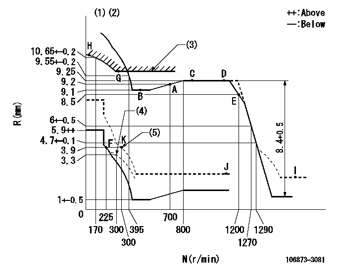
N:Pump speed
R:Rack position (mm)
(1)Tolerance for racks not indicated: +-0.05mm.
(2)Set idle at point K (N = N1, R = R1) and confirm that the injection quantity does not exceed Q1 at point J (N = N2).
(3)Excess fuel setting for starting: SXL
(4)Damper spring setting
(5)When air cylinder is operating.
----------
N1=300r/min R1=3.9mm N2=1150r/min Q1=3mm3/st SXL=9.85+-0.1mm
----------
----------
N1=300r/min R1=3.9mm N2=1150r/min Q1=3mm3/st SXL=9.85+-0.1mm
----------
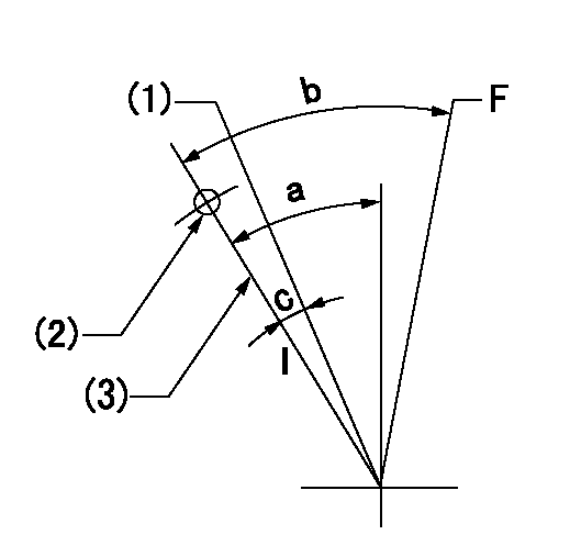
Speed control lever angle

F:Full speed
----------
----------
a=15.5deg+-5deg
----------
----------
a=15.5deg+-5deg
0000000901
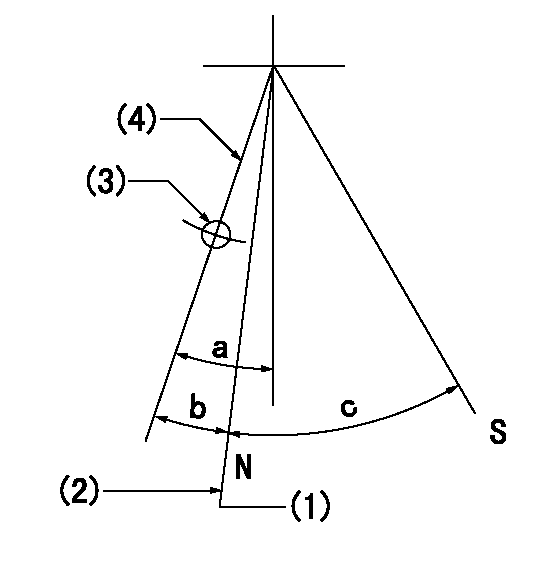
F:Full load
I:Idle
(1)When setting point K (at air cylinder operation)
(2)Use the hole at R = aa
(3)Stopper bolt setting
----------
aa=39mm
----------
a=39deg+-5deg b=43.5deg+-3deg c=(5deg)+-5deg
----------
aa=39mm
----------
a=39deg+-5deg b=43.5deg+-3deg c=(5deg)+-5deg
Stop lever angle
N:Pump normal
S:Stop the pump.
(1)Rack position = aa (at delivery), set before governor adjustment
(2)Set the stopper bolt (apply red paint).
(3)Use the pin at R = bb
(4)Lever free
----------
aa=12+-0.1mm bb=37mm
----------
a=(9deg)+-5deg b=9deg+-5deg c=35deg+-5deg
----------
aa=12+-0.1mm bb=37mm
----------
a=(9deg)+-5deg b=9deg+-5deg c=35deg+-5deg
0000001501 LEVER

1. Air cylinder adjustment
(1)With the load lever in the idle position, temporarily set the distance between the load lever A and the air cylinder D at approximately L.
(2)Set N1 and apply P1 to the air cylinder D.
(3)Adjust set bolt (D) to obtain R1 at the same speed.
(4)Lock using nut C.
(5)Apply positive pressure several times.
(6)Confirm that the load lever A returns to the idling position N2 at pressure P2.
(7)Also at P1 confirm R1 (N1).
----------
L=(5)mm R1=3.9mm N1=300r/min N2=225r/min P1=392+98kPa(4+1kgf/cm2) P2=0kPa(0kgf/cm2)
----------
----------
L=(5)mm R1=3.9mm N1=300r/min N2=225r/min P1=392+98kPa(4+1kgf/cm2) P2=0kPa(0kgf/cm2)
----------
Timing setting

(1)Pump vertical direction
(2)Coupling's key groove position at No 1 cylinder's beginning of injection
(3)-
(4)-
----------
----------
a=(80deg)
----------
----------
a=(80deg)
Information:
Coolant
At operating temperature, the engine coolant is hot and under pressure. The cooling system and all lines to heaters or the engine contain hot liquid. When pressure is relieved rapidly, this hot liquid can turn into steam.Allow cooling system components to cool before draining. Any contact with hot liquid or steam can cause severe burns. Check the coolant level only after the engine has been stopped and the vent release valve is cool enough to remove with your bare hand.Remove the cooling system vent release valve slowly to relieve pressure. Use caution when removing vent release valve, grease fittings, pressure taps, breathers or drain plugs. Hold a rag over the cap or plug to prevent being sprayed or splashed by liquids under pressure.Cooling system additive (conditioner) contains alkali. To prevent personal injury, avoid contact with the skin and eyes and do not drink.Oils
Hot oil and components can cause personal injury. Do not allow hot oil or components to contact the skin.Keep all exhaust manifold and turbocharger shields in place to protect hot exhaust from oil spray in the event of a line, tube or seal failure.Batteries
Always wear protective glasses when working with batteries. Battery electrolyte contains acid and can cause injury. Avoid contact with the skin and eyes.Wash hands after touching batteries and connectors. Use of gloves is recommended.Do not smoke when observing the battery electrolyte levels. Batteries give off flammable fumes which can explode. Ensure there is proper ventilation for batteries which are located in an enclosure.Never disconnect any charging unit circuit or battery circuit cable from the battery when charging unit is operating. A spark can cause the flammable vapor mixture of hydrogen and oxygen to explode.Fire or Explosion Prevention
Fire may result from lubricating oil or fuel sprayed on hot surfaces causing personal injury and property damage. Inspect all lines and tubes for wear or deterioration. They must be routed, supported or clamped securely. Tighten all connections to the recommended torque. Leaks can cause fires.Determine whether the engine will be operated in an environment in which combustible gases could be drawn through the air inlet system. These gases could cause the engine to overspeed, which in turn could seriously damage the engine and result in bodily injury or property damage.If your application involves the presence of combustible gases, consult your Caterpillar dealer to obtain additional information concerning protection devices suitable for the application involved.All fuels, most lubricants and some coolant mixtures are flammable. Diesel fuel is flammable. Gasoline is flammable. The mixture of diesel and gasoline fumes are extremely explosive.Do not smoke while refueling or in a refueling area.Do not smoke in areas where batteries are charged, or where flammable materials are stored.Always thaw a frozen battery before jump starting. Frozen batteries may explode. Batteries give off flammable fumes which can explode.Keep all fuels and lubricants stored in properly marked containers and away from all unauthorized persons.Store all oily rags or other flammable material in a protective container, in a safe place.Do not weld or flame