Information injection-pump assembly
ZEXEL
106873-3070
1068733070
HINO
220007870A
220007870a
Rating:
Cross reference number
ZEXEL
106873-3070
1068733070
HINO
220007870A
220007870a
Zexel num
Bosch num
Firm num
Name
Calibration Data:
Adjustment conditions
Test oil
1404 Test oil ISO4113 or {SAEJ967d}
1404 Test oil ISO4113 or {SAEJ967d}
Test oil temperature
degC
40
40
45
Nozzle and nozzle holder
105780-8140
Bosch type code
EF8511/9A
Nozzle
105780-0000
Bosch type code
DN12SD12T
Nozzle holder
105780-2080
Bosch type code
EF8511/9
Opening pressure
MPa
17.2
Opening pressure
kgf/cm2
175
Injection pipe
Outer diameter - inner diameter - length (mm) mm 8-3-600
Outer diameter - inner diameter - length (mm) mm 8-3-600
Overflow valve
134424-0820
Overflow valve opening pressure
kPa
127
107
147
Overflow valve opening pressure
kgf/cm2
1.3
1.1
1.5
Tester oil delivery pressure
kPa
157
157
157
Tester oil delivery pressure
kgf/cm2
1.6
1.6
1.6
Direction of rotation (viewed from drive side)
Right R
Right R
Injection timing adjustment
Direction of rotation (viewed from drive side)
Right R
Right R
Injection order
1-8-6-2-
7-5-4-3
Pre-stroke
mm
4.8
4.74
4.8
Beginning of injection position
Drive side NO.1
Drive side NO.1
Difference between angles 1
Cal 1-8 deg. 45 44.75 45.25
Cal 1-8 deg. 45 44.75 45.25
Difference between angles 2
Cal 1-6 deg. 90 89.75 90.25
Cal 1-6 deg. 90 89.75 90.25
Difference between angles 3
Cyl.1-2 deg. 135 134.75 135.25
Cyl.1-2 deg. 135 134.75 135.25
Difference between angles 4
Cal 1-7 deg. 180 179.75 180.25
Cal 1-7 deg. 180 179.75 180.25
Difference between angles 5
Cal 1-5 deg. 225 224.75 225.25
Cal 1-5 deg. 225 224.75 225.25
Difference between angles 6
Cal 1-4 deg. 270 269.75 270.25
Cal 1-4 deg. 270 269.75 270.25
Difference between angles 7
Cal 1-3 deg. 315 314.75 315.25
Cal 1-3 deg. 315 314.75 315.25
Injection quantity adjustment
Adjusting point
A
Rack position
8.9
Pump speed
r/min
700
700
700
Average injection quantity
mm3/st.
139.3
137.3
141.3
Max. variation between cylinders
%
0
-2
2
Basic
*
Fixing the lever
*
Injection quantity adjustment_02
Adjusting point
B
Rack position
8.95+-0.
5
Pump speed
r/min
1100
1100
1100
Average injection quantity
mm3/st.
133.1
129.1
137.1
Fixing the lever
*
Injection quantity adjustment_03
Adjusting point
F
Rack position
3.8+-0.5
Pump speed
r/min
225
225
225
Average injection quantity
mm3/st.
10.4
7.4
13.4
Max. variation between cylinders
%
0
-15
15
Fixing the rack
*
Injection quantity adjustment_04
Adjusting point
G
Rack position
-
Pump speed
r/min
100
100
100
Average injection quantity
mm3/st.
139
139
Fixing the lever
*
Remarks
After startup boost setting
After startup boost setting
Timer adjustment
Pump speed
r/min
750--
Advance angle
deg.
0
0
0
Load
1/4
Remarks
Start
Start
Timer adjustment_02
Pump speed
r/min
700
Advance angle
deg.
0.3
Load
1/4
Timer adjustment_03
Pump speed
r/min
820--
Advance angle
deg.
0.7
0.4
1
Load
4/4
Timer adjustment_04
Pump speed
r/min
900+50
Advance angle
deg.
0.7
0.4
1
Load
3/4
Timer adjustment_05
Pump speed
r/min
1100-50
Advance angle
deg.
5.25
4.95
5.55
Load
4/4
Remarks
Finish
Finish
Test data Ex:
Governor adjustment
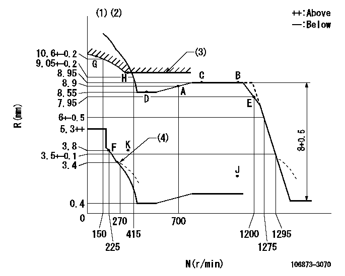
N:Pump speed
R:Rack position (mm)
(1)Tolerance for racks not indicated: +-0.05mm.
(2)Set idle at point K (N = N1, R = R1) and confirm that the injection quantity does not exceed Q1 at point J (N = N2).
(3)Excess fuel setting for starting: SXL
(4)Damper spring setting
----------
N1=325r/min R1=3.8mm N2=1100r/min Q1=3mm3/st SXL=10.25+-0.1mm
----------
----------
N1=325r/min R1=3.8mm N2=1100r/min Q1=3mm3/st SXL=10.25+-0.1mm
----------
Speed control lever angle

F:Full speed
----------
----------
a=(23deg)+-5deg
----------
----------
a=(23deg)+-5deg
0000000901

F:Full load
I:Idle
(1)Use the hole at R = aa
(2)Stopper bolt setting
----------
aa=42mm
----------
a=39deg+-5deg b=43.5deg+-3deg
----------
aa=42mm
----------
a=39deg+-5deg b=43.5deg+-3deg
Stop lever angle
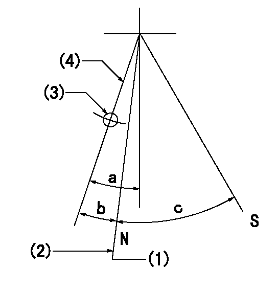
N:Pump normal
S:Stop the pump.
(1)Rack position = aa (at delivery), set before governor adjustment
(2)Set the stopper bolt (apply red paint).
(3)Use the pin at R = bb
(4)Lever free
----------
aa=12+-0.1mm bb=37mm
----------
a=(9deg)+-5deg b=9deg+-5deg c=35deg+-5deg
----------
aa=12+-0.1mm bb=37mm
----------
a=(9deg)+-5deg b=9deg+-5deg c=35deg+-5deg
Timing setting

(1)Pump vertical direction
(2)Coupling's key groove position at No 1 cylinder's beginning of injection
(3)-
(4)-
----------
----------
a=(80deg)
----------
----------
a=(80deg)
Information:
Emissions Warranty
Caterpillar Inc. warrants to the initial owner and subsequent owner of a diesel truck engines (powering on-highway trucks), that such engine is ...1. Designed, built and equipped so as to conform, at the time of sale, with all applicable regulations adopted by the United States Environmental Protection Agency (EPA).2. Free from defects in materials and workmanship in specific emission related parts for a period of 60 months, 100,000 miles (161 000 km) or 3,000 hours of operation, whichever occurs first, after date of delivery to the initial owner.If an emission related part fails during the warranty period, it will be repaired or replaced. Any such part repaired or replaced under warranty is warranted for the remainder of the warranty period.During the term of this warranty, Caterpillar Inc. will provide through a Caterpillar dealer or other establishment authorized by it, repair or replacement of any warranted part at no charge to the truck engine owner.In an emergency, repairs may be performed at any service establishment, or by the owner, using any replacement part.Caterpillar Inc. will reimburse the owner for their expenses, including diagnostic charges for such emergency repair. These expenses shall not exceed Caterpillar Inc. suggested retail price for all warranted parts replaced, and labor charges based on Caterpillar Inc. recommended time allowance for the warranty repair and the geographically appropriate hourly labor rate.As a condition of reimbursement, replaced parts and receipted invoices must be presented at a place of business of a Caterpillar dealer or other establishment authorized by Caterpillar Inc.Limitations & Responsibilities
The warranty is subject to the following:Caterpillar Inc. Responsibilities
During the emission warranty period, if a defect in material or workmanship of an emission related part or component is found, Caterpillar Inc. will provide:* New, Remanufactured or repaired parts and/or components, approved pursuant to EPA Regulations, required to correct the defect. Items replaced under this warranty become the property of Caterpillar Inc.* Reasonable and customary labor, during normal working hours, required to make the warranty repair. This includes labor to remove and install the engine, if necessary.Owner Responsibilities
During the emission warranty period, the owner is responsible for:* Premium or overtime labor costs, unless essential to prevent loss to perishable goods.* Costs to investigate complaints which are not caused by a defect in Caterpillar Inc. material or workmanship.* Providing timely notice of a warrantable failure and promptly making the product available for repair.Limitations
Caterpillar Inc. is not responsible for resultant damages to an emission related part or component resulting from:* Any application or installation Caterpillar Inc. deems improper.* Attachments, accessory items or parts not sold nor approved by Caterpillar Inc.* Improper truck engine maintenance, repair or abuse.* Owner's unreasonable delay in making the product available after being notified of a potential product problem.This warranty is in addition to Caterpillar Inc. standard warranty, applicable to the truck engine product involved.Remedies under this warranty are limited to the provision of material and services as specified herein. Caterpillar Inc. is not responsible for incidental or consequential damages.