Information injection-pump assembly
ZEXEL
106873-3061
1068733061

Rating:
Cross reference number
ZEXEL
106873-3061
1068733061
Zexel num
Bosch num
Firm num
Name
106873-3061
INJECTION-PUMP ASSEMBLY
Calibration Data:
Adjustment conditions
Test oil
1404 Test oil ISO4113 or {SAEJ967d}
1404 Test oil ISO4113 or {SAEJ967d}
Test oil temperature
degC
40
40
45
Nozzle and nozzle holder
105780-8140
Bosch type code
EF8511/9A
Nozzle
105780-0000
Bosch type code
DN12SD12T
Nozzle holder
105780-2080
Bosch type code
EF8511/9
Opening pressure
MPa
17.2
Opening pressure
kgf/cm2
175
Injection pipe
Outer diameter - inner diameter - length (mm) mm 8-3-600
Outer diameter - inner diameter - length (mm) mm 8-3-600
Overflow valve
134424-0820
Overflow valve opening pressure
kPa
127
107
147
Overflow valve opening pressure
kgf/cm2
1.3
1.1
1.5
Tester oil delivery pressure
kPa
157
157
157
Tester oil delivery pressure
kgf/cm2
1.6
1.6
1.6
Direction of rotation (viewed from drive side)
Right R
Right R
Injection timing adjustment
Direction of rotation (viewed from drive side)
Right R
Right R
Injection order
1-8-6-2-
7-5-4-3
Pre-stroke
mm
4.5
4.44
4.5
Beginning of injection position
Drive side NO.1
Drive side NO.1
Difference between angles 1
Cal 1-8 deg. 45 44.75 45.25
Cal 1-8 deg. 45 44.75 45.25
Difference between angles 2
Cal 1-6 deg. 90 89.75 90.25
Cal 1-6 deg. 90 89.75 90.25
Difference between angles 3
Cyl.1-2 deg. 135 134.75 135.25
Cyl.1-2 deg. 135 134.75 135.25
Difference between angles 4
Cal 1-7 deg. 180 179.75 180.25
Cal 1-7 deg. 180 179.75 180.25
Difference between angles 5
Cal 1-5 deg. 225 224.75 225.25
Cal 1-5 deg. 225 224.75 225.25
Difference between angles 6
Cal 1-4 deg. 270 269.75 270.25
Cal 1-4 deg. 270 269.75 270.25
Difference between angles 7
Cal 1-3 deg. 315 314.75 315.25
Cal 1-3 deg. 315 314.75 315.25
Injection quantity adjustment
Adjusting point
A
Rack position
9.2
Pump speed
r/min
700
700
700
Average injection quantity
mm3/st.
157.6
155.6
159.6
Max. variation between cylinders
%
0
-2
2
Basic
*
Fixing the lever
*
Injection quantity adjustment_02
Adjusting point
B
Rack position
9.1
Pump speed
r/min
500
500
500
Average injection quantity
mm3/st.
160.7
157.7
163.7
Fixing the lever
*
Injection quantity adjustment_03
Adjusting point
E
Rack position
8.5
Pump speed
r/min
1200
1200
1200
Average injection quantity
mm3/st.
129
126
132
Fixing the lever
*
Injection quantity adjustment_04
Adjusting point
F
Rack position
3.9+-0.5
Pump speed
r/min
225
225
225
Average injection quantity
mm3/st.
12.6
9.6
15.6
Max. variation between cylinders
%
0
-15
15
Fixing the rack
*
Injection quantity adjustment_05
Adjusting point
G
Rack position
9.85+-0.
1
Pump speed
r/min
300
300
300
Average injection quantity
mm3/st.
178.5
174.5
182.5
Fixing the lever
*
Remarks
Startup boost setting
Startup boost setting
Injection quantity adjustment_06
Adjusting point
H
Rack position
-
Pump speed
r/min
100
100
100
Average injection quantity
mm3/st.
188
188
208
Fixing the lever
*
Remarks
After startup boost setting
After startup boost setting
Timer adjustment
Pump speed
r/min
600--
Advance angle
deg.
0
0
0
Load
1/4
Remarks
Start
Start
Timer adjustment_02
Pump speed
r/min
550
Advance angle
deg.
0.3
Load
1/4
Timer adjustment_03
Pump speed
r/min
700--
Advance angle
deg.
1
0.7
1.3
Load
4/4
Timer adjustment_04
Pump speed
r/min
900+50
Advance angle
deg.
1
0.7
1.3
Load
3/4
Timer adjustment_05
Pump speed
r/min
1100-50
Advance angle
deg.
4.75
4.45
5.05
Load
4/4
Remarks
Finish
Finish
Test data Ex:
Governor adjustment
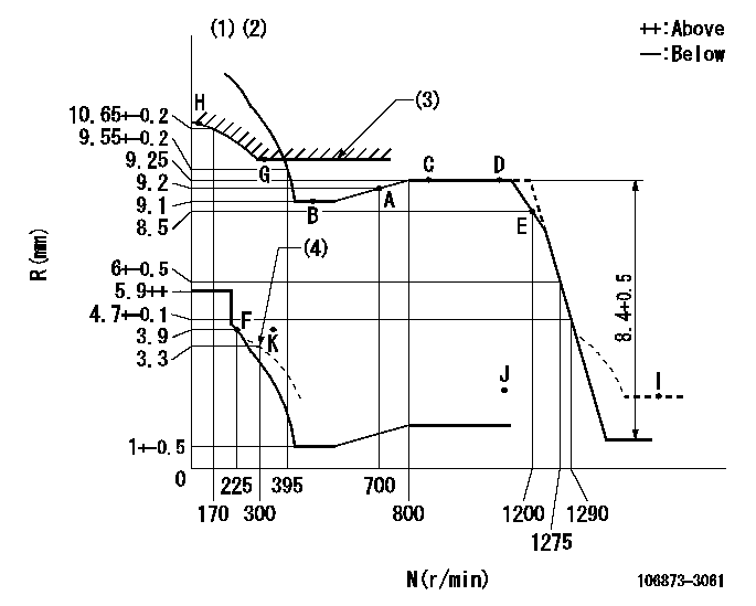
N:Pump speed
R:Rack position (mm)
(1)Tolerance for racks not indicated: +-0.05mm.
(2)Set idle at point K (N = N1, R = R1) and confirm that the injection quantity does not exceed Q1 at point J (N = N2).
(3)Excess fuel setting for starting: SXL
(4)Damper spring setting
----------
N1=300r/min R1=3.9mm N2=1150r/min Q1=3mm3/st SXL=9.85+-0.1mm
----------
----------
N1=300r/min R1=3.9mm N2=1150r/min Q1=3mm3/st SXL=9.85+-0.1mm
----------
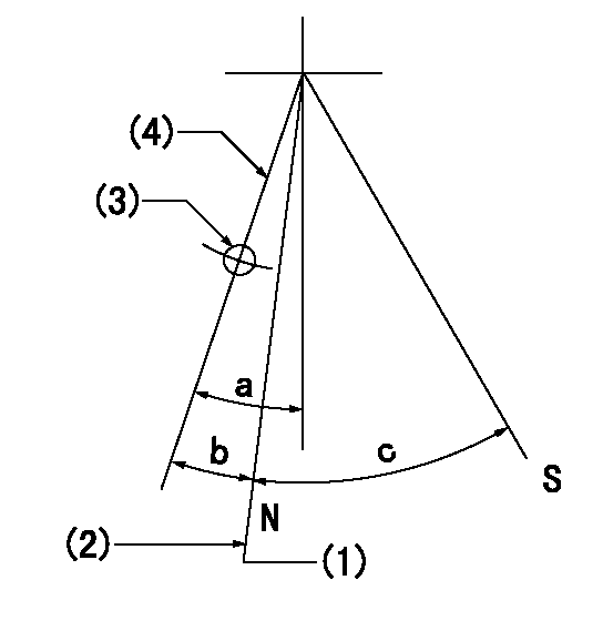
Speed control lever angle

F:Full speed
----------
----------
a=(15.5deg)+-5deg
----------
----------
a=(15.5deg)+-5deg
0000000901

F:Full load
I:Idle
(1)Use the hole at R = aa
(2)Stopper bolt setting
----------
aa=39mm
----------
a=39deg+-5deg b=43.5deg+-3deg
----------
aa=39mm
----------
a=39deg+-5deg b=43.5deg+-3deg
Stop lever angle
N:Pump normal
S:Stop the pump.
(1)Rack position = aa (at delivery), set before governor adjustment
(2)Set the stopper bolt (apply red paint).
(3)Use the pin at R = bb
(4)Lever free
----------
aa=12+-0.1mm bb=37mm
----------
a=(9deg)+-5deg b=9deg+-5deg c=35deg+-5deg
----------
aa=12+-0.1mm bb=37mm
----------
a=(9deg)+-5deg b=9deg+-5deg c=35deg+-5deg
Timing setting

(1)Pump vertical direction
(2)Coupling's key groove position at No 1 cylinder's beginning of injection
(3)-
(4)-
----------
----------
a=(80deg)
----------
----------
a=(80deg)
Information:
Bridge Adjustment
Intake and Exhaust Valve Mechanism
(1) Adjustment locknut, (2) Exhaust bridge, (3) Adjustment locknut, (4) Intake bridgeThe valve bridge should be checked and/or adjusted each time valve clearance is checked and/or adjusted. Valve and valve mechanism components do not always wear evenly which can allow the bridge to be out of adjustment.It is not necessary to remove the rocker arm shaft to adjust the valve bridges, but there must be clearance. Use the procedure that follows to make an adjustment to the bridge. Valves must be fully closed.1. Remove the valve covers from the engine.2. Lubricate the bridge dowel, bridge bore and the top pad of the bridge assembly with engine oil.3. While firmly pressing straight down on the bridge pad with a force of 1 to 10 lb (0.5 to 4.5 kg), turn the adjusting screw clockwise (CW) until contact is made with the valve stem.4. Turn the adjusting screw clockwise (CW) an additional 45° (1/8 turn) to straighten the dowel in the guide and compensate for slack in the threads.5. Hold the adjusting screw in this position and tighten the adjustment locknut to a torque of 18 5 lb ft (25 7 N m).6. Put engine oil at the point where the rocker arms make contact with the bridges.Valve Lash (Clearance) and Unit Injector Preload Adjustment
Valve clearance is measured between the rocker arm and the bridge for the valves.
Measure the valve lash with the engine stopped. To obtain an accurate measurement, allow at least 20 minutes for the valves to cool to engine cylinder head and block temperature.
When the valve lash (clearance) is checked, an adjustment is NOT necessary if the measurement is within the range given in the "Valve Clearance Check" chart shown. If the measurement is outside of the valve clearance check range shown, an adjustment is necessary. See the "Valve Clearance Setting" chart shown and make the setting to the nominal (desired) specifications in this chart. Adjust the valve clearance to within .003 in ( 0.08 mm) of the value given in the chart above.Rotate the engine crankshaft 360° in the normal crankshaft rotation direction before any adjustments are made. Operation of Caterpillar engines with improper valve adjustments will reduce engine efficiency. This reduced efficiency could result in excessive fuel usage and/or shortened engine component life.
Cylinder and Valve LocationTo make an adjustment to the valve clearance, turn the adjustment screw in the rocker arm. Valve clearance adjustments can be made by using the following procedure. The No. 1 piston must be at top center (TC) on the compression stroke. Follow the first three steps to find top center position for piston No. 1.
Locating Top Center for Piston No. 1
(1) Bolts (two - 6V5219), (2) Cover, (3) Flywheel Housing1. Remove two bolts (1) and remove cover (2) from the flywheel housing (3) to open the turning hole.2. Put one of the 6V5219 bolts in the timing hole located approximately 5 to 6 inches (127 to 152 mm) above the turning hole in
Have questions with 106873-3061?
Group cross 106873-3061 ZEXEL
Hino
Hino
Hino
Hino
106873-3061
INJECTION-PUMP ASSEMBLY