Information injection-pump assembly
ZEXEL
106873-3060
1068733060
HINO
220007860A
220007860a

Rating:
Cross reference number
ZEXEL
106873-3060
1068733060
HINO
220007860A
220007860a
Zexel num
Bosch num
Firm num
Name
Calibration Data:
Adjustment conditions
Test oil
1404 Test oil ISO4113 or {SAEJ967d}
1404 Test oil ISO4113 or {SAEJ967d}
Test oil temperature
degC
40
40
45
Nozzle and nozzle holder
105780-8140
Bosch type code
EF8511/9A
Nozzle
105780-0000
Bosch type code
DN12SD12T
Nozzle holder
105780-2080
Bosch type code
EF8511/9
Opening pressure
MPa
17.2
Opening pressure
kgf/cm2
175
Injection pipe
Outer diameter - inner diameter - length (mm) mm 8-3-600
Outer diameter - inner diameter - length (mm) mm 8-3-600
Overflow valve
134424-0820
Overflow valve opening pressure
kPa
127
107
147
Overflow valve opening pressure
kgf/cm2
1.3
1.1
1.5
Tester oil delivery pressure
kPa
157
157
157
Tester oil delivery pressure
kgf/cm2
1.6
1.6
1.6
Direction of rotation (viewed from drive side)
Right R
Right R
Injection timing adjustment
Direction of rotation (viewed from drive side)
Right R
Right R
Injection order
1-8-6-2-
7-5-4-3
Pre-stroke
mm
4.5
4.44
4.5
Beginning of injection position
Drive side NO.1
Drive side NO.1
Difference between angles 1
Cal 1-8 deg. 45 44.75 45.25
Cal 1-8 deg. 45 44.75 45.25
Difference between angles 2
Cal 1-6 deg. 90 89.75 90.25
Cal 1-6 deg. 90 89.75 90.25
Difference between angles 3
Cyl.1-2 deg. 135 134.75 135.25
Cyl.1-2 deg. 135 134.75 135.25
Difference between angles 4
Cal 1-7 deg. 180 179.75 180.25
Cal 1-7 deg. 180 179.75 180.25
Difference between angles 5
Cal 1-5 deg. 225 224.75 225.25
Cal 1-5 deg. 225 224.75 225.25
Difference between angles 6
Cal 1-4 deg. 270 269.75 270.25
Cal 1-4 deg. 270 269.75 270.25
Difference between angles 7
Cal 1-3 deg. 315 314.75 315.25
Cal 1-3 deg. 315 314.75 315.25
Injection quantity adjustment
Adjusting point
A
Rack position
9.2
Pump speed
r/min
700
700
700
Average injection quantity
mm3/st.
157.6
155.6
159.6
Max. variation between cylinders
%
0
-2
2
Basic
*
Fixing the lever
*
Injection quantity adjustment_02
Adjusting point
B
Rack position
9.1
Pump speed
r/min
500
500
500
Average injection quantity
mm3/st.
160.7
157.7
163.7
Fixing the lever
*
Injection quantity adjustment_03
Adjusting point
E
Rack position
8.5
Pump speed
r/min
1200
1200
1200
Average injection quantity
mm3/st.
129
126
132
Fixing the lever
*
Injection quantity adjustment_04
Adjusting point
F
Rack position
3.9+-0.5
Pump speed
r/min
225
225
225
Average injection quantity
mm3/st.
12.6
9.6
15.6
Max. variation between cylinders
%
0
-15
15
Fixing the rack
*
Injection quantity adjustment_05
Adjusting point
G
Rack position
9.85+-0.
1
Pump speed
r/min
300
300
300
Average injection quantity
mm3/st.
178.5
174.5
182.5
Fixing the lever
*
Remarks
Startup boost setting
Startup boost setting
Injection quantity adjustment_06
Adjusting point
H
Rack position
-
Pump speed
r/min
100
100
100
Average injection quantity
mm3/st.
188
188
208
Fixing the lever
*
Remarks
After startup boost setting
After startup boost setting
Timer adjustment
Pump speed
r/min
600--
Advance angle
deg.
0
0
0
Load
1/4
Remarks
Start
Start
Timer adjustment_02
Pump speed
r/min
550
Advance angle
deg.
0.3
Load
1/4
Timer adjustment_03
Pump speed
r/min
700--
Advance angle
deg.
1
0.7
1.3
Load
4/4
Timer adjustment_04
Pump speed
r/min
900+50
Advance angle
deg.
1
0.7
1.3
Load
3/4
Timer adjustment_05
Pump speed
r/min
1100-50
Advance angle
deg.
4.75
4.45
5.05
Load
4/4
Remarks
Finish
Finish
Test data Ex:
Governor adjustment
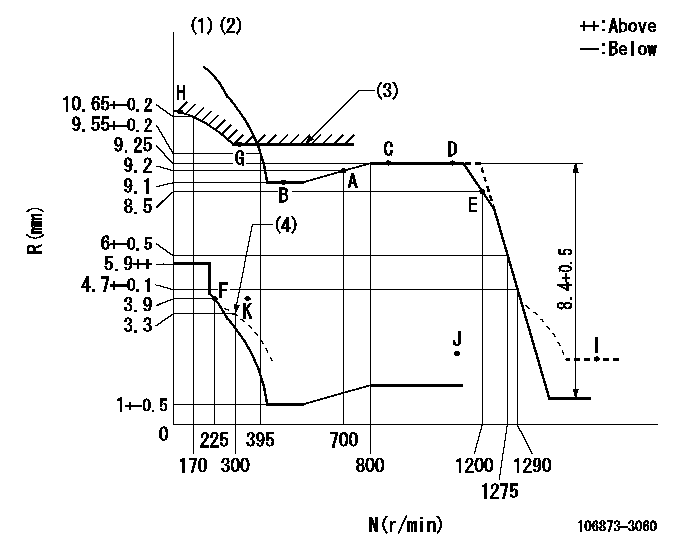
N:Pump speed
R:Rack position (mm)
(1)Tolerance for racks not indicated: +-0.05mm.
(2)Set idle at point K (N = N1, R = R1) and confirm that the injection quantity does not exceed Q1 at point J (N = N2).
(3)Excess fuel setting for starting: SXL
(4)Damper spring setting
----------
N1=300r/min R1=3.9mm N2=1150r/min Q1=3mm3/st SXL=9.85+-0.1mm
----------
----------
N1=300r/min R1=3.9mm N2=1150r/min Q1=3mm3/st SXL=9.85+-0.1mm
----------
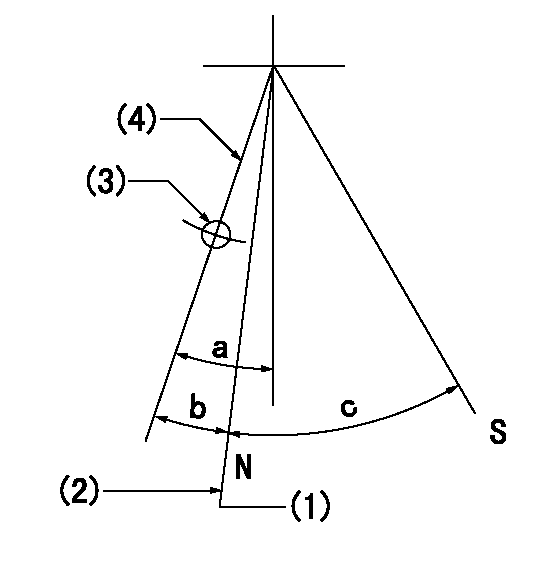
Speed control lever angle

F:Full speed
----------
----------
a=(22deg)+-5deg
----------
----------
a=(22deg)+-5deg
0000000901

F:Full load
I:Idle
(1)Use the hole at R = aa
(2)Stopper bolt setting
----------
aa=39mm
----------
a=39deg+-5deg b=43.5deg+-3deg
----------
aa=39mm
----------
a=39deg+-5deg b=43.5deg+-3deg
Stop lever angle
N:Pump normal
S:Stop the pump.
(1)Rack position = aa (at delivery), set before governor adjustment
(2)Set the stopper bolt (apply red paint).
(3)Use the pin at R = bb
(4)Lever free
----------
aa=12+-0.1mm bb=37mm
----------
a=(9deg)+-5deg b=9deg+-5deg c=35deg+-5deg
----------
aa=12+-0.1mm bb=37mm
----------
a=(9deg)+-5deg b=9deg+-5deg c=35deg+-5deg
Timing setting

(1)Pump vertical direction
(2)Coupling's key groove position at No 1 cylinder's beginning of injection
(3)-
(4)-
----------
----------
a=(80deg)
----------
----------
a=(80deg)
Information:
Crankcase Breather
Clean
1. Loosen hose clamp (1) and remove the hose from the cover.2. Loosen three breather cover bolts (2) and remove cover (3). 3. Remove breather element (4), and wash in clean, nonflammable solvent and allow to dry. 4. Install clean, dry breather element (4).5. Install cover (3) and bolts (2).5. Install hose and clamp (1). Tighten clamp (1), refer to topic "Torque Specifications" for the proper torque of hose clamp-worm drive band type. If the crankcase breather is not maintained on a regular basis, it will become plugged. A plugged crankcase breather would result in excessive crankcase pressure that may cause crankshaft seal leakage.Alternator, Fan and Accessory Drive Belts
Inspect/Replace
Inspect the condition and adjustment of alternator belts and fan drive belts.Inspect the drive belts for wear and replace if they show any signs of wear. If one belt in a set requires replacement, always install a new matched set of belts. Never replace just the worn belt. If only the worn belt is replaced, the new belt will carry all the load, as it will not be stretched as much as the older belts. All the belts will fail in rapid succession.Belt Adjustment
* To check the belt tension, apply 25 lbs (110 N) of force midway between the pulleys. Correctly adjusted belts will deflect 1/2 to 3/4 inch (13 to 19 mm).If belts are too loose, they vibrate enough to cause unnecessary wear on the belts and pulleys. If belts are too tight, unnecessary stresses are placed upon the pulley bearings and belts which might shorten the life of both.The engine is equipped with an automatic belt tensioner, adjustments should not be necessary.Hoses and Clamps
Inspect/Replace
Hose replacement prior to failure is a cost effective preventive maintenance practice. Replacing a hose before it fails saves money and reduces the chances for unscheduled downtime. By replacing a hose that is cracked, soft or leaking, you will avoid major repairs that could result in a severe engine overheating problem. * Inspect all hoses for leaks due to cracking, softness and loose clamps.* Replace hoses that are cracked or soft and tighten loose clamps.Before Replacing Hoses
1. After engine is cool, loosen the radiator filler cap slowly to relieve any pressure and remove the cap.2. Drain the coolant from the cooling system to a level below the hose being replaced.3. Remove the hose clamps, disconnect the old hose and replace with a new hose.4. Install hose clamps. (See the Torque for Standard Hose Clamps-Worm Band Type chart in the Torque Specifications section of this publication for the appropriate torque.) For constant torque hose clamps, see the Torque Specifications section in this publication.After Replacing Hoses
Refer to the Cooling System Specifications and Cooling System-Test for Coolant Additive maintenance topics in this publication.5. Add coolant mixture to the cooling system. Bring it to the proper level by mixing a solution of acceptable water and Caterpillar Antifreeze. Test for supplemental additive (Conditioner) concentration. Add proper amount, or if equipped with a coolant additive element, install the appropriate element