Information injection-pump assembly
ZEXEL
106873-3052
1068733052
HINO
220801572A
220801572a
Rating:
Cross reference number
ZEXEL
106873-3052
1068733052
HINO
220801572A
220801572a
Zexel num
Bosch num
Firm num
Name
Calibration Data:
Adjustment conditions
Test oil
1404 Test oil ISO4113 or {SAEJ967d}
1404 Test oil ISO4113 or {SAEJ967d}
Test oil temperature
degC
40
40
45
Nozzle and nozzle holder
105780-8140
Bosch type code
EF8511/9A
Nozzle
105780-0000
Bosch type code
DN12SD12T
Nozzle holder
105780-2080
Bosch type code
EF8511/9
Opening pressure
MPa
17.2
Opening pressure
kgf/cm2
175
Injection pipe
Outer diameter - inner diameter - length (mm) mm 8-3-600
Outer diameter - inner diameter - length (mm) mm 8-3-600
Overflow valve
134424-0820
Overflow valve opening pressure
kPa
127
107
147
Overflow valve opening pressure
kgf/cm2
1.3
1.1
1.5
Tester oil delivery pressure
kPa
157
157
157
Tester oil delivery pressure
kgf/cm2
1.6
1.6
1.6
Direction of rotation (viewed from drive side)
Right R
Right R
Injection timing adjustment
Direction of rotation (viewed from drive side)
Right R
Right R
Injection order
1-8-6-2-
7-5-4-3
Pre-stroke
mm
4.8
4.74
4.8
Beginning of injection position
Drive side NO.1
Drive side NO.1
Difference between angles 1
Cal 1-8 deg. 45 44.75 45.25
Cal 1-8 deg. 45 44.75 45.25
Difference between angles 2
Cal 1-6 deg. 90 89.75 90.25
Cal 1-6 deg. 90 89.75 90.25
Difference between angles 3
Cyl.1-2 deg. 135 134.75 135.25
Cyl.1-2 deg. 135 134.75 135.25
Difference between angles 4
Cal 1-7 deg. 180 179.75 180.25
Cal 1-7 deg. 180 179.75 180.25
Difference between angles 5
Cal 1-5 deg. 225 224.75 225.25
Cal 1-5 deg. 225 224.75 225.25
Difference between angles 6
Cal 1-4 deg. 270 269.75 270.25
Cal 1-4 deg. 270 269.75 270.25
Difference between angles 7
Cal 1-3 deg. 315 314.75 315.25
Cal 1-3 deg. 315 314.75 315.25
Injection quantity adjustment
Adjusting point
A
Rack position
8.9
Pump speed
r/min
700
700
700
Average injection quantity
mm3/st.
139.3
137.3
141.3
Max. variation between cylinders
%
0
-2
2
Basic
*
Fixing the lever
*
Injection quantity adjustment_02
Adjusting point
B
Rack position
8.95+-0.
5
Pump speed
r/min
1100
1100
1100
Average injection quantity
mm3/st.
133.1
129.1
137.1
Fixing the lever
*
Injection quantity adjustment_03
Adjusting point
E
Rack position
3.8+-0.5
Pump speed
r/min
225
225
225
Average injection quantity
mm3/st.
10.4
7.4
13.4
Max. variation between cylinders
%
0
-15
15
Fixing the rack
*
Injection quantity adjustment_04
Adjusting point
F
Rack position
-
Pump speed
r/min
100
100
100
Average injection quantity
mm3/st.
139
139
Fixing the lever
*
Remarks
After startup boost setting
After startup boost setting
Timer adjustment
Pump speed
r/min
750--
Advance angle
deg.
0
0
0
Load
1/4
Remarks
Start
Start
Timer adjustment_02
Pump speed
r/min
700
Advance angle
deg.
0.3
Load
1/4
Timer adjustment_03
Pump speed
r/min
820--
Advance angle
deg.
0.7
0.4
1
Load
4/4
Timer adjustment_04
Pump speed
r/min
900+50
Advance angle
deg.
0.7
0.4
1
Load
3/4
Timer adjustment_05
Pump speed
r/min
1100-50
Advance angle
deg.
5.25
4.95
5.55
Load
4/4
Remarks
Finish
Finish
Test data Ex:
Governor adjustment
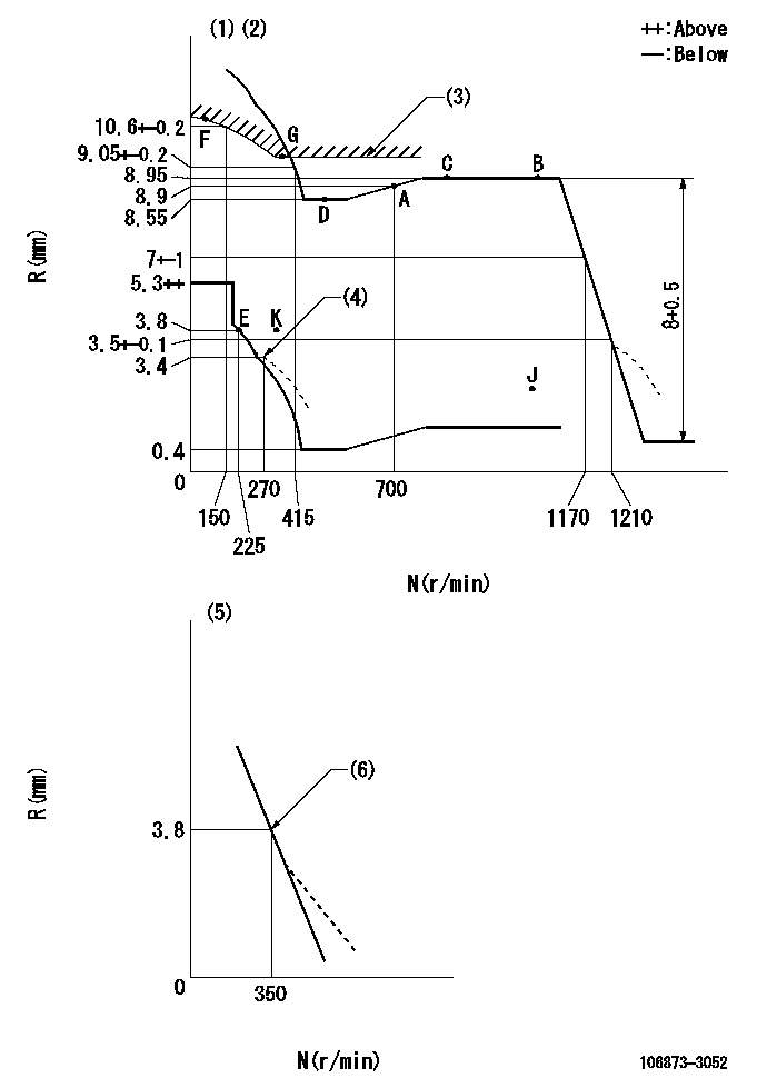
N:Pump speed
R:Rack position (mm)
(1)Tolerance for racks not indicated: +-0.05mm.
(2)Set idle at point K (N = N1, R = R1) and confirm that the injection quantity does not exceed Q1 at point J (N = N2).
(3)Excess fuel setting for starting: SXL
(4)Damper spring setting
(5)Variable speed specification: idling adjustment
(6)Main spring setting
----------
N1=325r/min R1=3.8mm N2=1100rmin Q1=3mm3/st SXL=10.25+-0.1mm
----------
----------
N1=325r/min R1=3.8mm N2=1100rmin Q1=3mm3/st SXL=10.25+-0.1mm
----------
Speed control lever angle

F:Full speed
I:Idle
(1)Stopper bolt setting
----------
----------
a=(19deg)+-5deg b=19deg+-5deg
----------
----------
a=(19deg)+-5deg b=19deg+-5deg
0000000901

F:Full load
I:Idle
(1)Use the hole at R = aa
(2)Stopper bolt setting
----------
aa=42mm
----------
a=39deg+-5deg b=43.5deg+-3deg
----------
aa=42mm
----------
a=39deg+-5deg b=43.5deg+-3deg
Stop lever angle
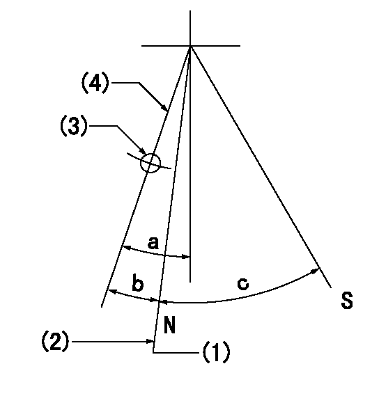
N:Pump normal
S:Stop the pump.
(1)Rack position = aa (at delivery), set before governor adjustment
(2)Set the stopper bolt (apply red paint).
(3)Use the pin at R = bb
(4)Lever free
----------
aa=12+-0.1mm bb=37mm
----------
a=(9deg)+-5deg b=9deg+-5deg c=35deg+-5deg
----------
aa=12+-0.1mm bb=37mm
----------
a=(9deg)+-5deg b=9deg+-5deg c=35deg+-5deg
0000001501 LEVER

2-stage changeover lever adjustment
(A) Speed lever
(B) Load lever
(C) 2-stage changeover lever
(D) Link
(E) Bolt
(G) Variable speed specifications
(H) Minimum maximum speed specifications
F:Full speed
I:Idle
1. Minimum-maximum speed specification adjustment (when running)
(1)After completing governor adjustment, hold the 2-stage changeover lever (C) so that the speed lever (A) contacts the full speed stopper.
(2)In this condition, the load lever is held in the idle position.
(3)Adjust bolt (E) so that the clearance between the pin underneath lever (C) and the end of the long groove in link (D) is L.
(4)Lock using the nut.
2. Variable speed specification adjustment (at operation)
(1)Hold the 2-stage changeover lever (C) so that the load lever (B) contacts the full load stopper. (When the load lever is equipped with a cancel mechanism, move it so that it contacts the stopper without canceling.)
(2)In this condition, confirm that the speed lever (A) moves from idle to full speed.
----------
L=1~2mm
----------
----------
L=1~2mm
----------
Timing setting

(1)Pump vertical direction
(2)Coupling's key groove position at No 1 cylinder's beginning of injection
(3)-
(4)-
----------
----------
a=(80deg)
----------
----------
a=(80deg)
Information:
Caterpillar's Scheduled Oil Sampling (S O S) is the best indicator for determining what is happening inside your engine.S O S is a diagnostic tool used to determine oil performance and component wear rates with a series of tests designed to identify and measure contamination such as soot, sulfur, etc. and degradation such as the presence of fuel, water and antifreeze in a sample of oil.The tests also determine the amount of wear metals present in the oil sample, which is compared to established Caterpillar norms to determine acceptability. To be effective as an indicator, S O S must be performed on a continuing basis. Intermittent sampling will not allow wear rate trend lines to be established. Obtain at PM Level 1
Obtain S O S samples at regularly scheduled intervals to monitor the condition and maintenance requirements of your engine. Each oil sample should be taken when the oil is warm and well mixed to ensure that the sample is representative of the oil in the engine crankcase.Consult your Caterpillar dealer for complete information and assistance in establishing an S O S program for your engine(s).S O S Analysis
S O S is composed of three basic tests:* Wear Analysis* Chemical and Physical Tests* Oil Condition Analysis Wear analysis is performed with an atomic absorption spectrophotometer to monitor component wear by identifying and measuring concentrations, in parts per million, of wear elements present in the oil. Based on known normal concentration data, maximum limits ofwear elements are established. Impending failures can be identified when test results deviate from concentration levels established as acceptable, based on normal wear. Chemical and physical tests detect the presence of water, fuel and glycol (antifreeze) in the oil and determine whether or not their concentrations exceed established maximum limits. Oil condition is evaluated with infrared analysis. This test determines the presence and measures the amount of contaminants such as soot, sulfur products, oxidation, and nitration products in the oil. Infrared analysis can also assist in customizing (reducing maintaining or extending) oil change intervals for particular conditions and applications.Infrared analysis should always be accompanied by wear element analysis and chemical and physical tests to assure accurate diagnosis. Infrared analysis must be used to determine oil change intervals. S O S must include Infrared (IR) in the analysis.The test results of the oil samples will then be used as a basis for determining the oil change interval for your engine, giving you the ultimate time between oil changes without the risk of engine damage.Refer to Caterpillar pamphlet Scheduled Oil Sampling, form PEDP7105 for information and benefits of S O S.