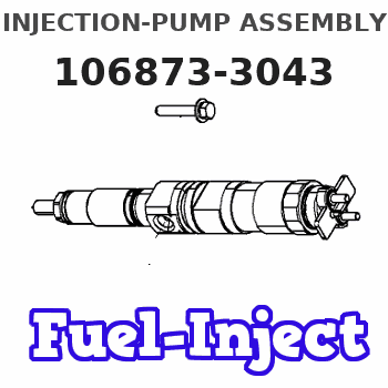
Information injection-pump assembly
ZEXEL
106873-3043
1068733043
Rating:
Cross reference number
ZEXEL
106873-3043
1068733043
Zexel num
Bosch num
Firm num
Name
106873-3043
INJECTION-PUMP ASSEMBLY
Calibration Data:
Adjustment conditions
Test oil
1404 Test oil ISO4113 or {SAEJ967d}
1404 Test oil ISO4113 or {SAEJ967d}
Test oil temperature
degC
40
40
45
Nozzle and nozzle holder
105780-8140
Bosch type code
EF8511/9A
Nozzle
105780-0000
Bosch type code
DN12SD12T
Nozzle holder
105780-2080
Bosch type code
EF8511/9
Opening pressure
MPa
17.2
Opening pressure
kgf/cm2
175
Injection pipe
Outer diameter - inner diameter - length (mm) mm 8-3-600
Outer diameter - inner diameter - length (mm) mm 8-3-600
Overflow valve
134424-0820
Overflow valve opening pressure
kPa
127
107
147
Overflow valve opening pressure
kgf/cm2
1.3
1.1
1.5
Tester oil delivery pressure
kPa
157
157
157
Tester oil delivery pressure
kgf/cm2
1.6
1.6
1.6
Direction of rotation (viewed from drive side)
Right R
Right R
Injection timing adjustment
Direction of rotation (viewed from drive side)
Right R
Right R
Injection order
1-8-6-2-
7-5-4-3
Pre-stroke
mm
4.8
4.74
4.8
Beginning of injection position
Drive side NO.1
Drive side NO.1
Difference between angles 1
Cal 1-8 deg. 45 44.75 45.25
Cal 1-8 deg. 45 44.75 45.25
Difference between angles 2
Cal 1-6 deg. 90 89.75 90.25
Cal 1-6 deg. 90 89.75 90.25
Difference between angles 3
Cyl.1-2 deg. 135 134.75 135.25
Cyl.1-2 deg. 135 134.75 135.25
Difference between angles 4
Cal 1-7 deg. 180 179.75 180.25
Cal 1-7 deg. 180 179.75 180.25
Difference between angles 5
Cal 1-5 deg. 225 224.75 225.25
Cal 1-5 deg. 225 224.75 225.25
Difference between angles 6
Cal 1-4 deg. 270 269.75 270.25
Cal 1-4 deg. 270 269.75 270.25
Difference between angles 7
Cal 1-3 deg. 315 314.75 315.25
Cal 1-3 deg. 315 314.75 315.25
Injection quantity adjustment
Adjusting point
A
Rack position
8.9
Pump speed
r/min
700
700
700
Average injection quantity
mm3/st.
139.3
137.3
141.3
Max. variation between cylinders
%
0
-2
2
Basic
*
Fixing the lever
*
Injection quantity adjustment_02
Adjusting point
B
Rack position
8.95+-0.
5
Pump speed
r/min
1100
1100
1100
Average injection quantity
mm3/st.
133.1
129.1
137.1
Fixing the lever
*
Injection quantity adjustment_03
Adjusting point
F
Rack position
3.8+-0.5
Pump speed
r/min
225
225
225
Average injection quantity
mm3/st.
10.4
7.4
13.4
Max. variation between cylinders
%
0
-15
15
Fixing the rack
*
Injection quantity adjustment_04
Adjusting point
G
Rack position
-
Pump speed
r/min
100
100
100
Average injection quantity
mm3/st.
139
139
Fixing the lever
*
Remarks
After startup boost setting
After startup boost setting
Timer adjustment
Pump speed
r/min
750--
Advance angle
deg.
0
0
0
Load
1/4
Remarks
Start
Start
Timer adjustment_02
Pump speed
r/min
700
Advance angle
deg.
0.3
Load
1/4
Timer adjustment_03
Pump speed
r/min
820--
Advance angle
deg.
0.7
0.4
1
Load
4/4
Timer adjustment_04
Pump speed
r/min
900+50
Advance angle
deg.
0.7
0.4
1
Load
3/4
Timer adjustment_05
Pump speed
r/min
1100-50
Advance angle
deg.
5.25
4.95
5.55
Load
4/4
Remarks
Finish
Finish
Test data Ex:
Governor adjustment

N:Pump speed
R:Rack position (mm)
(1)Lever ratio: RT
(2)Target shim dimension: TH
(3)Tolerance for racks not indicated: +-0.05mm.
(4)Excess fuel setting for starting: SXL
(5)Damper spring setting
(6)Set idle at point K (N = N1, R = R1) and confirm that the injection quantity does not exceed Q1 at point J (N = N2).
----------
RT=0.8 TH=2.7mm SXL=9.45+-0.1mm N1=325r/min R1=3.8mm N2=1100r/min Q1=3mm3/st
----------
----------
RT=0.8 TH=2.7mm SXL=9.45+-0.1mm N1=325r/min R1=3.8mm N2=1100r/min Q1=3mm3/st
----------
Speed control lever angle

F:Full speed
----------
----------
a=15.5deg+-5deg
----------
----------
a=15.5deg+-5deg
0000000901

F:Full load
I:Idle
(1)Use the hole at R = aa
(2)Stopper bolt setting
----------
aa=42mm
----------
a=39deg+-5deg b=43.5deg+-3deg
----------
aa=42mm
----------
a=39deg+-5deg b=43.5deg+-3deg
Stop lever angle
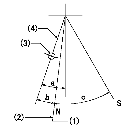
N:Pump normal
S:Stop the pump.
(1)Rack position = aa (at delivery), set before governor adjustment
(2)Set the stopper bolt (apply red paint).
(3)Use the pin at R = bb
(4)Lever free
----------
aa=12+-0.1mm bb=37mm
----------
a=(9deg)+-5deg b=9deg+-5deg c=35deg+-5deg
----------
aa=12+-0.1mm bb=37mm
----------
a=(9deg)+-5deg b=9deg+-5deg c=35deg+-5deg
0000001501 RACK SENSOR

(VR) measurement voltage
(I) Part number of the control unit
(G) Apply red paint.
(H): End surface of the pump
1. Rack sensor adjustment (-0620)
(1)Fix the speed control lever at the full position
(2)Set the speed to N1 r/min.
(If the boost compensator is provided, apply boost pressure.)
(3)Adjust the bobbin (A) so that the rack sensor's output voltage is VR+-0.01.
(4)At that time, rack position must be Ra.
(5)Apply G at two places.
Connecting part between the joint (B) and the nut (F)
Connecting part between the joint (B) and the end surface of the pump (H)
----------
N1=1100r/min Ra=(8.95)mm
----------
----------
N1=1100r/min Ra=(8.95)mm
----------
Timing setting

(1)Pump vertical direction
(2)Coupling's key groove position at No 1 cylinder's beginning of injection
(3)-
(4)-
----------
----------
a=(80deg)
----------
----------
a=(80deg)
Information:
Engine Lifting
When it is necessary to remove a component on an angle, remember that the capacity of an eyebolt is less as the angle between the supporting members and the object becomes less than 90°. Eyebolts and brackets should never be bent and should only be loaded in tension.
Use a hoist to remove heavy components. Lift the engine by using an adjustable lifting beam. All supporting members (chains and cables) should be parallel to each other, and as near perpendicular as possible to the top of the object being lifted.Some removals require the use of lifting fixtures to obtain proper balance and to provide safe handling. To remove the engine, use the two lifting eyes on the engine.Lifting eyes are designed for the arrangement as sold. Alterations to lifting eyes and/or arrangement weight make the lifting devices obsolete.If you make alterations, you are responsible for providing adequate lifting devices.Engine Storage
If the engine is not started for several weeks, the lubricating oil will drain from the cylinder walls and piston rings. Rust can form on the cylinder liner surface, which will increase engine wear and result in shorter engine life.To prevent excessive engine wear:
Be sure all lubrication recommendations mentioned in the Maintenance Management Schedule intervals chart are completed.If freezing temperatures can be expected, check the cooling system for adequate protection against freezing. A 50/50 solution of Caterpillar permanent-type antifreeze and approved water will give protection below -20°F (-29°C).If it will be impossible to start the engine every week, consult your Caterpillar dealer for instructions to prepare your engine for longer storage periods.If an engine remains out of service and its use is not immediately planned, special precautions should be taken.Refer to "Storage Procedures For Caterpillar Products," Form SEHS9031 for more detailed information on engine storage.
Have questions with 106873-3043?
Group cross 106873-3043 ZEXEL
Hino
106873-3043
INJECTION-PUMP ASSEMBLY